Robotrontechnik-Forum

Registrieren || Einloggen || Hilfe/FAQ || Suche || Mitglieder || Home || Statistik || Kalender || Admins Willkommen Gast! RSS

Robotrontechnik-Forum » Technische Diskussionen » Robotron A5120 - Help needed! » Themenansicht

Autor Thread - Seiten: -1-
000
08.03.2016, 23:03 Uhr
asbesto

Avatar von asbesto

Hi there,

I'm sorry but I don't speak German - so for me is very difficult to search and check for technical information. So I'm asking for help!

We recently acquired a Robotron A5120 - fantastic computer!
And we're trying to fix it so it can work again!

The machine itself came from a very bad shipping, in bad conditions: plastics cracked and so I had to fix and patch the exterior things together. It was a very bad shipping

Next, I check every board, connections, I looked at power supplies, I connected everything, cleaned connections, check fuses, and cables, etc.

I did some test on some power supply capacitors, they seem ok and I think can be reformed or maybe they can work again with no problem at all.

I removed every board, checked the video section, reconnected video cables that were detached (high voltage and monitor). With every board disconnected, I tried powering up the system.

And nothing happened. No light, Nothing from the frontal LED's. Nothing!

I double checked connections, tried again, nothing.

So I thinked that some board must be inserted to power on the computer from the keyboard, and so I connected some boards (cpu, keyboard) and I tried again.

Nothing.

Double checked fuses, they are ok. But I can't measure any voltage anywhere.

And so I'm stuck.

I made a photo album here:

http://zaverio.com/~asbesto/robotron/

I really hope someone can help us!

Thank you everyone,

Gabriele
--
---
73 de IW9HGS
asbesto@gmail.com
Museo dell'Informatica Funzionante Computer Museum
http://museum.freaknet.org
Seitenanfang Seitenende
Profil || Private Nachricht || Suche Zitatantwort || Editieren || Löschen
001
09.03.2016, 11:28 Uhr
holm

Avatar von holm

You must connect the Keyboard properly to the CPU PCB (that PCB with the two U880s on them IMG 20160308 171444) and insert it to the correct slot of the Card Cage. You can then switch on the power with the green power button on the Keyboard (one time pressed power on, 2 times reset, 3 times power off).

If that doesn't work you have a fault in the "Schaltkassette" .. (power sequencer box) in the lowest part (basement) of the computer. Down there should be at least one LED lit if power is connected to the computer, depending of the state of the power sequencer more LEDs.. If there is no light, you have to repair the PSU or the sequencer (IMG 20160308 171711).

Even if all that is working you wouldn't see any picture (besides of some garbage depending on the video card) on the monitor. The bootstrap code on the CPU board has only 1kbye and doesn't contain any display text. You must load an OS from the floppy drives to actually see something. If the computer tries to boot you should see the LEDs on the floppy drives lit up one after the other. You need a bootable disk, do you have one?

This is an old Version of the BC A5120 with 200KByte single side floppy drives. (40 tracks).
The Key mechanism ( IMG 20160308 174218) on the keyboard has no meaning for you at the first time, plug it in and leave it alone..


..an die Anderen hier, ich habe keinen solchen A5120, welche LEDs im Keller müssen leuchten?

Regards,

Holm
--
float R,y=1.5,x,r,A,P,B;int u,h=80,n=80,s;main(c,v)int c;char **v;
{s=(c>1?(h=atoi(v[1])):h)*h/2;for(R=6./h;s%h||(y-=R,x=-2),s;4<(P=B*B)+
(r=A*A)|++u==n&&putchar(*(((--s%h)?(u<n?--u%6:6):7)+"World! \n"))&&
(A=B=P=u=r=0,x+=R/2))A=B*2*A+y,B=P+x-r;}

Dieser Beitrag wurde am 09.03.2016 um 13:10 Uhr von holm editiert.
Seitenanfang Seitenende
Profil || Private Nachricht || Suche Zitatantwort || Editieren || Löschen
002
09.03.2016, 12:05 Uhr
ADDERLY


Hoffentlich weiss er auf was er sich da einlaesst
--
Gruss Frank

"Lieber Gott,: Bitte schmeiss Hirn vom Himmel; ...oder Steine, Hauptsache Du triffst Jemanden !..."
...und 'ne Tuete Schweineohr'n
Seitenanfang Seitenende
Profil || Private Nachricht || Suche Zitatantwort || Editieren || Löschen
003
09.03.2016, 12:13 Uhr
DL
Default Group and Edit


Zuerst muß mal das Standby Netzteil laufen, da leuchten die beiden linken LED, dann kann man über Einschalten nachdenken
Seitenanfang Seitenende
Profil || Private Nachricht || Suche Zitatantwort || Editieren || Löschen
004
09.03.2016, 12:49 Uhr
TTL-Grab


Hi Gabriele,

did You really check all fuses? Besides the two at the rear there are some hidden on boards in the bottom below the monitor assembly and the crate, as well as into the power bricks.
Eastern German fuses, and therefor the holders too, tend to corrode heavily over the time.

Micha
Seitenanfang Seitenende
Profil || Private Nachricht || Suche Zitatantwort || Editieren || Löschen
005
09.03.2016, 17:38 Uhr
asbesto

Avatar von asbesto

Thank you all for answers! I fixed the RF filter - was shorted or interrupted, 220V didn't pass thru it. I opened - a lot of wax stuff came out. I replaced part of it with new capacitors and filters, and put everything into the original box.

After that I tried, and nothing happened. So I removed the screen and in the board under it I found the blown fuse and a blown capacitor (20uF / 385V). I think this can be the cause. I will check the board for other faults.

Do you think there are any capacitor to be changed to prevent any damage, especially in the 2 PSU (5V and 12V)?

Thank you,

Gabriele
--
---
73 de IW9HGS
asbesto@gmail.com
Museo dell'Informatica Funzionante Computer Museum
http://museum.freaknet.org
Seitenanfang Seitenende
Profil || Private Nachricht || Suche Zitatantwort || Editieren || Löschen
006
09.03.2016, 17:53 Uhr
holm

Avatar von holm

The Capacitors in the STM Modules (PSU) should be fine..don't know for now if the 5120 contains a STZ Module (don't think so) if yes, there are more elektrolytics from that 20µF 385V Type in there that may be bad, check for broken rubber seals on them.
Check the fuse holders in the STM modules too and clean them if necessary. (that hint above regarding corroded fuses and fuse holders was meant to be real..)

BTW: the PSU Controller Chip called B260D is compatible to the TDA1060 .. just in case you want to find faults.. If a PSU isn't working first change the small Electrolytics around the B260, specially if they are made by Roederstein (BRD) and not Frolyt (GDR).

...we all hope that your HV Transformer is still healthy ....

Regards,

Holm
--
float R,y=1.5,x,r,A,P,B;int u,h=80,n=80,s;main(c,v)int c;char **v;
{s=(c>1?(h=atoi(v[1])):h)*h/2;for(R=6./h;s%h||(y-=R,x=-2),s;4<(P=B*B)+
(r=A*A)|++u==n&&putchar(*(((--s%h)?(u<n?--u%6:6):7)+"World! \n"))&&
(A=B=P=u=r=0,x+=R/2))A=B*2*A+y,B=P+x-r;}

Dieser Beitrag wurde am 09.03.2016 um 17:54 Uhr von holm editiert.
Seitenanfang Seitenende
Profil || Private Nachricht || Suche Zitatantwort || Editieren || Löschen
007
09.03.2016, 17:56 Uhr
asbesto

Avatar von asbesto

I can't read the value of the fuse. Any help? (yes, in the PSU board)

And, where can I find schematics of this (and other) boards? Will be very useful now

Danke!
--
---
73 de IW9HGS
asbesto@gmail.com
Museo dell'Informatica Funzionante Computer Museum
http://museum.freaknet.org

Dieser Beitrag wurde am 09.03.2016 um 17:57 Uhr von asbesto editiert.
Seitenanfang Seitenende
Profil || Private Nachricht || Suche Zitatantwort || Editieren || Löschen
008
09.03.2016, 18:46 Uhr
holm

Avatar von holm

The Fuse should be 160mA. I think the Schematic you need is similar to this one:

http://www.tiffe.de/Robotron/K8924/Standby.jpg

..it is from a different but very similar Computer (K8924), it isn't unlikely that it is the same.
Check for the PCB Number..

Regards,

Holm
--
float R,y=1.5,x,r,A,P,B;int u,h=80,n=80,s;main(c,v)int c;char **v;
{s=(c>1?(h=atoi(v[1])):h)*h/2;for(R=6./h;s%h||(y-=R,x=-2),s;4<(P=B*B)+
(r=A*A)|++u==n&&putchar(*(((--s%h)?(u<n?--u%6:6):7)+"World! \n"))&&
(A=B=P=u=r=0,x+=R/2))A=B*2*A+y,B=P+x-r;}

Dieser Beitrag wurde am 09.03.2016 um 18:47 Uhr von holm editiert.
Seitenanfang Seitenende
Profil || Private Nachricht || Suche Zitatantwort || Editieren || Löschen
009
09.03.2016, 19:15 Uhr
Greon


The same diagram with some notes about voltages that should being measured:

It's from a A5120.

Regards,
Olaf

Dieser Beitrag wurde am 09.03.2016 um 19:18 Uhr von Greon editiert.
Seitenanfang Seitenende
Profil || Private Nachricht || Suche Zitatantwort || Editieren || Löschen
010
09.03.2016, 22:00 Uhr
asbesto

Avatar von asbesto

Weird. I measure 220 volt at the input of the board, and also at the AC input of the little rectifier bridge. But, at the output "+" and "-" and also at the 22uF/400V capacitor (that I changed) I measure... 28 Volt!


Tomorrow I will do some check, but I can't understand why I have 28v dc instead of about 240 !

PS I added new pictures at http://zaverio.com/~asbesto/robotron

the reparation goes on!
--
---
73 de IW9HGS
asbesto@gmail.com
Museo dell'Informatica Funzionante Computer Museum
http://museum.freaknet.org
Seitenanfang Seitenende
Profil || Private Nachricht || Suche Zitatantwort || Editieren || Löschen
011
09.03.2016, 22:04 Uhr
holm

Avatar von holm

..there is only one conclusion: the rectifier is bad.

Regards,

Holm
--
float R,y=1.5,x,r,A,P,B;int u,h=80,n=80,s;main(c,v)int c;char **v;
{s=(c>1?(h=atoi(v[1])):h)*h/2;for(R=6./h;s%h||(y-=R,x=-2),s;4<(P=B*B)+
(r=A*A)|++u==n&&putchar(*(((--s%h)?(u<n?--u%6:6):7)+"World! \n"))&&
(A=B=P=u=r=0,x+=R/2))A=B*2*A+y,B=P+x-r;}
Seitenanfang Seitenende
Profil || Private Nachricht || Suche Zitatantwort || Editieren || Löschen
012
09.03.2016, 23:44 Uhr
asbesto

Avatar von asbesto

I tested it outside the circuit, and it's OK!
--
---
73 de IW9HGS
asbesto@gmail.com
Museo dell'Informatica Funzionante Computer Museum
http://museum.freaknet.org
Seitenanfang Seitenende
Profil || Private Nachricht || Suche Zitatantwort || Editieren || Löschen
013
10.03.2016, 00:58 Uhr
constanze czech

Avatar von constanze czech

Keep an eye on the thermistor near the big transistor (The thing with the wires). We had this part faulty several times.
--
biete 3-Raum-Computer 96m², Dusche, WC, Zentralheizung, Ferritkerngrill...(nicht ganz) ruhige Wohnlage....zum Zeitwert...
Seitenanfang Seitenende
Profil || Private Nachricht || Suche Zitatantwort || Editieren || Löschen
014
10.03.2016, 13:22 Uhr
asbesto

Avatar von asbesto

OK, this morning I checked out something.

I have 300V on the 22uF/400V capacitor, so rectifier is ok. Maybe I was wrong measuring yesterday.

I tested the SU165 transistor and it seem OK (my Atlas DCA55 say it's a diode network, but I tested by hand with my analogic tester and seem ok).

Holm, when you said "...we all hope that your HV Transformer is still healthy ...." you mean L6 in the schematic? I just desoldered it, it seem OK looking at it, I measure those values on pins:

1-2 0.46 ohm 0.17mH
3-4 1.50 ohm 4.56mH
5-6 0.50 ohm 0.09mH
7-8 0.34 ohm 0.02mH

Are those values OK?
--
---
73 de IW9HGS
asbesto@gmail.com
Museo dell'Informatica Funzionante Computer Museum
http://museum.freaknet.org
Seitenanfang Seitenende
Profil || Private Nachricht || Suche Zitatantwort || Editieren || Löschen
015
10.03.2016, 13:26 Uhr
holm

Avatar von holm

..don't know about the Transformer you measured..and don't think that it has a problem..
I think that PSU had the faulty electrolytic as main failure, put it together again and try
to power it up (..connect an 230V 100W light bulb in series fist time)

No, I meant the Flyback Transformer in the Monitor Chassis, the one with the yellowish coil..
We don't have a solution for a replacement at the moment, besides of winding a new one per hand..


Regards,

Holm
--
float R,y=1.5,x,r,A,P,B;int u,h=80,n=80,s;main(c,v)int c;char **v;
{s=(c>1?(h=atoi(v[1])):h)*h/2;for(R=6./h;s%h||(y-=R,x=-2),s;4<(P=B*B)+
(r=A*A)|++u==n&&putchar(*(((--s%h)?(u<n?--u%6:6):7)+"World! \n"))&&
(A=B=P=u=r=0,x+=R/2))A=B*2*A+y,B=P+x-r;}

Dieser Beitrag wurde am 10.03.2016 um 13:29 Uhr von holm editiert.
Seitenanfang Seitenende
Profil || Private Nachricht || Suche Zitatantwort || Editieren || Löschen
016
10.03.2016, 14:09 Uhr
asbesto

Avatar von asbesto

I was wondering about how to preserve that HV transformer.

I mean, some time ago I used a sort of hand-made varnish made with a solvent and poly-stirene dissolved in it.

I used it to protect some circuit parts suffering high voltage discharge, is an effective insulation method, can be applied as a paint, and become a solid transparent plastic, high insulating and stable.

It was good for high voltage transformers, so I wonder if maybe I can apply this on the HV transformer BEFORE turning it on for the first time, just to protect it from arc discharges.

beside that, I'm just testing other components, just found some high ESR electrolytics so... stay tuned, and thank you for help
--
---
73 de IW9HGS
asbesto@gmail.com
Museo dell'Informatica Funzionante Computer Museum
http://museum.freaknet.org
Seitenanfang Seitenende
Profil || Private Nachricht || Suche Zitatantwort || Editieren || Löschen
017
10.03.2016, 15:55 Uhr
holm

Avatar von holm

Unfortunaltely there isn't much you can do to save the FBT. There is a Problem with the internal isolation from the HV coil wich consists of some (russian) acetate film. It seems that, if the outer Isolation is broken somewhere, humidity gets in and generates some vinegar acid if high field strengths occur.
You can smell it when it occurs and all our tries to prevent that have failed in the past.

Some buddies here wound their own coils with success.. try searching for the subject ÜHA78 here.


Regards,

Holm
--
float R,y=1.5,x,r,A,P,B;int u,h=80,n=80,s;main(c,v)int c;char **v;
{s=(c>1?(h=atoi(v[1])):h)*h/2;for(R=6./h;s%h||(y-=R,x=-2),s;4<(P=B*B)+
(r=A*A)|++u==n&&putchar(*(((--s%h)?(u<n?--u%6:6):7)+"World! \n"))&&
(A=B=P=u=r=0,x+=R/2))A=B*2*A+y,B=P+x-r;}
Seitenanfang Seitenende
Profil || Private Nachricht || Suche Zitatantwort || Editieren || Löschen
018
10.03.2016, 16:02 Uhr
asbesto

Avatar von asbesto

Thank you for the information, I hope our can be working.

I tested all other components in the board. I found thyristor ST103/1 is totally open / blown, and also the diac KR206 seem to be open but I can't test it further. I assume it's ok...

This is good news as I finally found the problem!

Bad news is that I can't find KR206 on ebay or other places, so I think I need some compatible DIAC. I don't know if it's faulty, I hope not.

Any hint?

Thank you all, this forum is fantastic and really I need to learn German!
--
---
73 de IW9HGS
asbesto@gmail.com
Museo dell'Informatica Funzionante Computer Museum
http://museum.freaknet.org

Dieser Beitrag wurde am 10.03.2016 um 16:19 Uhr von asbesto editiert.
Seitenanfang Seitenende
Profil || Private Nachricht || Suche Zitatantwort || Editieren || Löschen
019
10.03.2016, 17:18 Uhr
asbesto

Avatar von asbesto

About the HV transformer - it seem in perfect shape, no cracks at all, no vinegar smell. I think coating it with high voltage protective varnish can help his life. Will decide later
--
---
73 de IW9HGS
asbesto@gmail.com
Museo dell'Informatica Funzionante Computer Museum
http://museum.freaknet.org
Seitenanfang Seitenende
Profil || Private Nachricht || Suche Zitatantwort || Editieren || Löschen
020
10.03.2016, 18:12 Uhr
holm

Avatar von holm

Any Diac will do, ER900 for example. The KR206 was a tzech manufacture (Tesla). The ST103 Thyristor is
an 100V 3A Type, (sure that it is defective?) a similar one will do the job.

The K206 should become conductive at approx. 34V.
Is the Zener SYX21/12, V7 still ok? (12V 400mW Type).

Regards,

Holm
--
float R,y=1.5,x,r,A,P,B;int u,h=80,n=80,s;main(c,v)int c;char **v;
{s=(c>1?(h=atoi(v[1])):h)*h/2;for(R=6./h;s%h||(y-=R,x=-2),s;4<(P=B*B)+
(r=A*A)|++u==n&&putchar(*(((--s%h)?(u<n?--u%6:6):7)+"World! \n"))&&
(A=B=P=u=r=0,x+=R/2))A=B*2*A+y,B=P+x-r;}
Seitenanfang Seitenende
Profil || Private Nachricht || Suche Zitatantwort || Editieren || Löschen
021
10.03.2016, 18:37 Uhr
asbesto

Avatar von asbesto

Yes, that Zener is ok.

I desoldered an identical ST103/1 from the other board, and tested it - it's ok, so this one is definitively broken, it doesn't become conductive at all.

Just ordered the Tesla thyristor So I think I have to wait some days, here I can't buy anything anywhere.

Thank you!
--
---
73 de IW9HGS
asbesto@gmail.com
Museo dell'Informatica Funzionante Computer Museum
http://museum.freaknet.org

Dieser Beitrag wurde am 10.03.2016 um 18:38 Uhr von asbesto editiert.
Seitenanfang Seitenende
Profil || Private Nachricht || Suche Zitatantwort || Editieren || Löschen
022
10.03.2016, 19:39 Uhr
holm

Avatar von holm

grmbl...ask before ordering. It should be possible to put such things from the parts bin in a letter to italy..

BTW: The ST103 is east German made, the KR206 was from Tesla.

Regards,

Holm
--
float R,y=1.5,x,r,A,P,B;int u,h=80,n=80,s;main(c,v)int c;char **v;
{s=(c>1?(h=atoi(v[1])):h)*h/2;for(R=6./h;s%h||(y-=R,x=-2),s;4<(P=B*B)+
(r=A*A)|++u==n&&putchar(*(((--s%h)?(u<n?--u%6:6):7)+"World! \n"))&&
(A=B=P=u=r=0,x+=R/2))A=B*2*A+y,B=P+x-r;}
Seitenanfang Seitenende
Profil || Private Nachricht || Suche Zitatantwort || Editieren || Löschen
023
10.03.2016, 19:40 Uhr
holm

Avatar von holm

k.t.
--
float R,y=1.5,x,r,A,P,B;int u,h=80,n=80,s;main(c,v)int c;char **v;
{s=(c>1?(h=atoi(v[1])):h)*h/2;for(R=6./h;s%h||(y-=R,x=-2),s;4<(P=B*B)+
(r=A*A)|++u==n&&putchar(*(((--s%h)?(u<n?--u%6:6):7)+"World! \n"))&&
(A=B=P=u=r=0,x+=R/2))A=B*2*A+y,B=P+x-r;}

Dieser Beitrag wurde am 10.03.2016 um 19:47 Uhr von holm editiert.
Seitenanfang Seitenende
Profil || Private Nachricht || Suche Zitatantwort || Editieren || Löschen
024
11.03.2016, 12:58 Uhr
asbesto

Avatar von asbesto

...and so I'm waiting for the spare parts to come.

Is there anything I can check while waiting for them? Other boards? Parts of the computer? Whatever? I dont wanna just sit and wait
--
---
73 de IW9HGS
asbesto@gmail.com
Museo dell'Informatica Funzionante Computer Museum
http://museum.freaknet.org
Seitenanfang Seitenende
Profil || Private Nachricht || Suche Zitatantwort || Editieren || Löschen
025
11.03.2016, 14:07 Uhr
holm

Avatar von holm

There is not that much you can do w/o Power ...

You can try to form the Capacitors in the PSU Modules, but if you want to test the Modules you need a load and have to bridge some of the contacts at the backside. Not that easy w/o an proper extra connector handy.

Do you have the necessary boot floppies? Otherwise creating them should be it's own little challenge for the time you have to wait, but I think you will have more things to fix on the PCB's.

You are hanging around the top of an PDP11 :-) ..but how good are your Z80 skills?
The BC A5120 is using a special Kind of DMA Access for the FDC. Since the Z80 DMA wasn't available from the semiconductor industry in the GDR at the time the A5120 was build, it has a 2nd CPU that gets preloaded to build a DMA (using the ini instruction) for the FDC, the FDC requests the bus which disables the main CPU and enables the DMA CPU to get the transfer done if a byte is available, an interrupt context switch isn't necessary this way.

Look for the K1520 BUS description and print it out, for sure you will need it...

..you do not know what you loaded up yourselves :-)

Regards,

Holm
--
float R,y=1.5,x,r,A,P,B;int u,h=80,n=80,s;main(c,v)int c;char **v;
{s=(c>1?(h=atoi(v[1])):h)*h/2;for(R=6./h;s%h||(y-=R,x=-2),s;4<(P=B*B)+
(r=A*A)|++u==n&&putchar(*(((--s%h)?(u<n?--u%6:6):7)+"World! \n"))&&
(A=B=P=u=r=0,x+=R/2))A=B*2*A+y,B=P+x-r;}

Dieser Beitrag wurde am 11.03.2016 um 15:57 Uhr von holm editiert.
Seitenanfang Seitenende
Profil || Private Nachricht || Suche Zitatantwort || Editieren || Löschen
026
11.03.2016, 15:24 Uhr
asbesto

Avatar von asbesto

Wow! I used to program Z80 assembly many, many years ago

Well fortunately we have about 30 disks for this computer so I think we can be able to boot it. We need to copy them with our recovery station setup here, this is an upcoming task.

I hope they will boot, at least one of them.

What you all didn't know, is that we're going to show this computer in an exibithion in Rome so I'm kinda in a hurry to fix it - otherwise we will show it without turning it on

Today I'm washing plastics / resin parts, putting pieces together (the shipping smashed them a lot!) and cleaning stuff around...
--
---
73 de IW9HGS
asbesto@gmail.com
Museo dell'Informatica Funzionante Computer Museum
http://museum.freaknet.org
Seitenanfang Seitenende
Profil || Private Nachricht || Suche Zitatantwort || Editieren || Löschen
027
11.03.2016, 15:51 Uhr
holm

Avatar von holm

:-)

When you have some spare time you can take a look inside the K5600 floppy drives, especiall to the umbrella like plastic
spider that centers the discs. This peace is a little bit overengeneered and unnecessary
complicated in that Type of drives and tend to destroy itself over time..as Rüdiger reported here...

http://www.robotrontechnik.de/html/forum/thwb/showtopic.php?threadid=5625
http://www.robotrontechnik.de/index.htm?/html/komponenten/fs.htm

Regards,


Holm
--
float R,y=1.5,x,r,A,P,B;int u,h=80,n=80,s;main(c,v)int c;char **v;
{s=(c>1?(h=atoi(v[1])):h)*h/2;for(R=6./h;s%h||(y-=R,x=-2),s;4<(P=B*B)+
(r=A*A)|++u==n&&putchar(*(((--s%h)?(u<n?--u%6:6):7)+"World! \n"))&&
(A=B=P=u=r=0,x+=R/2))A=B*2*A+y,B=P+x-r;}

Dieser Beitrag wurde am 11.03.2016 um 15:52 Uhr von holm editiert.
Seitenanfang Seitenende
Profil || Private Nachricht || Suche Zitatantwort || Editieren || Löschen
028
11.03.2016, 22:38 Uhr
asbesto

Avatar von asbesto

I fixed one of the drives - the umbrella was disconnected from his hub. I put a lot of effort studying this AMAZING MECHANISM, and I succeed in putting it back. It's an incredible device. Yes, it's overengineered

The other 2 drives are ok.

Many damages here are due to the bad packaging. We're searching for another robotron, if one of them is around please let us know. Our Museum want to specialize in eastern hardware, because... it's AMAZING!

Really I never saw anything so good engineered as this computer
--
---
73 de IW9HGS
asbesto@gmail.com
Museo dell'Informatica Funzionante Computer Museum
http://museum.freaknet.org
Seitenanfang Seitenende
Profil || Private Nachricht || Suche Zitatantwort || Editieren || Löschen
029
19.03.2016, 15:41 Uhr
asbesto

Avatar von asbesto

OK, finally I received the thyristor, the diode, and some other things. So I changed the thyristor, the output 6.2V zener diode that was shorted... and... nothing happens again

I'm trying to figure out what's wrong. Pin 1 of the B260 chip have only 0.6V instead of, maybe, 12V.

And after a while I found the problem: the damn fuse holder! OK to my eyes, but measuring contacts... I had about 1 Kiloohm between the fuse and the pcb trace!

I simply changed it - and now the power supply board give a stable 5V

Now I have 2 LED turned on at the diag panel (the 2 left, looking at the front of the computer) and I have a led ON on the keyboard, near the "CI" key.

But the computer doesn't turn on. I press the "power" green button, but nothing happens.

Last 3 picture here (http://zaverio.com/~asbesto/robotron/) show the led and the position of keyboard plug, I'm pretty sure it's correct.

Any idea so far?
--
---
73 de IW9HGS
asbesto@gmail.com
Museo dell'Informatica Funzionante Computer Museum
http://museum.freaknet.org

Dieser Beitrag wurde am 19.03.2016 um 19:48 Uhr von asbesto editiert.
Seitenanfang Seitenende
Profil || Private Nachricht || Suche Zitatantwort || Editieren || Löschen
030
19.03.2016, 20:21 Uhr
Greon


On IMG 20160309 172936 you can find a green and a yellow LED at the back side. Both should be on.
If so, you can measure the signal on pin 3 of the second IC on the left side. It should be high normaly and go to low if you press the green power button.
Seitenanfang Seitenende
Profil || Private Nachricht || Suche Zitatantwort || Editieren || Löschen
031
19.03.2016, 21:21 Uhr
asbesto

Avatar von asbesto

Ach! I think only the green one is on, and the yellow is off!
--
---
73 de IW9HGS
asbesto@gmail.com
Museo dell'Informatica Funzionante Computer Museum
http://museum.freaknet.org
Seitenanfang Seitenende
Profil || Private Nachricht || Suche Zitatantwort || Editieren || Löschen
032
19.03.2016, 22:13 Uhr
Greon


I am sorry, i have been wrong. Only the green one ist OK. The yellow will light, if the main relay gets voltage.
What about the pin 3 signal?
Seitenanfang Seitenende
Profil || Private Nachricht || Suche Zitatantwort || Editieren || Löschen
033
20.03.2016, 12:23 Uhr
asbesto

Avatar von asbesto

Ok. the pin 3 signal on that chip (D100D) give me 3.8V.

When I press the (I) (on) button on the keyboard, it goes off (0 volt) and come back 3.8v in a few seconds.

When I press 3 times, the green led goes off, stay off for some time, and come back on.

Chip D100D is powered, 5V is fine.

(I edited this message a lot, had problems testing )
--
---
73 de IW9HGS
asbesto@gmail.com
Museo dell'Informatica Funzionante Computer Museum
http://museum.freaknet.org

Dieser Beitrag wurde am 20.03.2016 um 12:50 Uhr von asbesto editiert.
Seitenanfang Seitenende
Profil || Private Nachricht || Suche Zitatantwort || Editieren || Löschen
034
20.03.2016, 12:45 Uhr
holm

Avatar von holm

The D100 is an 7400.

Regards,

Holm
--
float R,y=1.5,x,r,A,P,B;int u,h=80,n=80,s;main(c,v)int c;char **v;
{s=(c>1?(h=atoi(v[1])):h)*h/2;for(R=6./h;s%h||(y-=R,x=-2),s;4<(P=B*B)+
(r=A*A)|++u==n&&putchar(*(((--s%h)?(u<n?--u%6:6):7)+"World! \n"))&&
(A=B=P=u=r=0,x+=R/2))A=B*2*A+y,B=P+x-r;}
Seitenanfang Seitenende
Profil || Private Nachricht || Suche Zitatantwort || Editieren || Löschen
035
20.03.2016, 12:53 Uhr
asbesto

Avatar von asbesto

Yes I saw it on google Keypress goes on pin 1 and 2 (3.8, 3.9V) and exit on pin 3 (3.82v) so it seem that the chip is OK. power (5v) seem good on all the board.

But nothing happens and the computer doesn't start
--
---
73 de IW9HGS
asbesto@gmail.com
Museo dell'Informatica Funzionante Computer Museum
http://museum.freaknet.org
Seitenanfang Seitenende
Profil || Private Nachricht || Suche Zitatantwort || Editieren || Löschen
036
20.03.2016, 13:25 Uhr
asbesto

Avatar von asbesto

I'm looking at this schematic:

http://www.robotrontechnik.de/bilder/Upload_Forum/16/jz_523.png

So, I must measure if pressing ON I have 24V output on "Rel" pin of the Netzteuerung board. If so, probably I must check the "Thermosicherung (J)" on the X15 connector, because can interrupt the circuit and block the relais engagement.

Does it sound good?
--
---
73 de IW9HGS
asbesto@gmail.com
Museo dell'Informatica Funzionante Computer Museum
http://museum.freaknet.org
Seitenanfang Seitenende
Profil || Private Nachricht || Suche Zitatantwort || Editieren || Löschen
037
20.03.2016, 14:20 Uhr
DL
Default Group and Edit


The Pin "relais" from "Netzsteuerung" must switch from 24V to zero if you pressing ON. The 24v source comes from "24P intern"
Seitenanfang Seitenende
Profil || Private Nachricht || Suche Zitatantwort || Editieren || Löschen
038
20.03.2016, 16:19 Uhr
Greon


I thought, actually, of the IC left beside it - but anyway, the reaction of the green LED is a good sign!
I you can measure 24 V on the "Rel" pin the "Thermosicherung" (thermal fuse) seems to be OK.
The relais control is a bit tricky. As a precaution i give you the diagramm:

and the layout
Seitenanfang Seitenende
Profil || Private Nachricht || Suche Zitatantwort || Editieren || Löschen
039
20.03.2016, 16:21 Uhr
asbesto

Avatar von asbesto

Well, I definitively found the problem!!!

The metallic transistors in the Netzteuerung board were totally smashed down the PCB, so legs were in short circuit, and also one of them was touching a resistor. You can see the problem here:

http://zaverio.com/~asbesto/robotron/tn/IMG_20160320_160850.jpg.html

I put them back in shape, very carefully, and the computer turned ON pressing the key!!!

And I can shut it down pressing the key 3 times - very slow, because if I press them fast, the machine turns off and then again ON.

I can't see anything on the screen - I can't even see the screen light.

Diagnostic LED don't turn on - I only have the 2 LED on, and the other four are OFF.

So I think something else need to be fixed

Help please!
--
---
73 de IW9HGS
asbesto@gmail.com
Museo dell'Informatica Funzionante Computer Museum
http://museum.freaknet.org

Dieser Beitrag wurde am 20.03.2016 um 16:26 Uhr von asbesto editiert.
Seitenanfang Seitenende
Profil || Private Nachricht || Suche Zitatantwort || Editieren || Löschen
040
20.03.2016, 16:28 Uhr
holm

Avatar von holm

Depending on the version of the video PCB this is normal. I've already wrote that somewhere above, you get a display only if the system is successfully booting, but it should be possible to adjust brightness and contrast so that you at least can see a raster displayed (in dark room).

Before you insert a bootdisk verify that the disk leds light up one after another if you turn the computer on and after an reset (button pressed 2 times).

Is the (2708) Erpom on the K2526 Board (CPU) socketed?

Edit: yes, it is..nice!

Do you have the ability to burn 2708 Eproms?

Regards,

Holm
--
float R,y=1.5,x,r,A,P,B;int u,h=80,n=80,s;main(c,v)int c;char **v;
{s=(c>1?(h=atoi(v[1])):h)*h/2;for(R=6./h;s%h||(y-=R,x=-2),s;4<(P=B*B)+
(r=A*A)|++u==n&&putchar(*(((--s%h)?(u<n?--u%6:6):7)+"World! \n"))&&
(A=B=P=u=r=0,x+=R/2))A=B*2*A+y,B=P+x-r;}

Dieser Beitrag wurde am 20.03.2016 um 16:32 Uhr von holm editiert.
Seitenanfang Seitenende
Profil || Private Nachricht || Suche Zitatantwort || Editieren || Löschen
041
20.03.2016, 16:48 Uhr
asbesto

Avatar von asbesto

Hmmm, I can't burn 2708 but 2732 instead.

A problem I just found is that a fuse blowed up in the 5V power supply and I can't read the value. The other one is good.

Is this one:

http://zaverio.com/~asbesto/robotron/tn/IMG_20160320_164629.jpg.html

2.5A 250V timed?
--
---
73 de IW9HGS
asbesto@gmail.com
Museo dell'Informatica Funzionante Computer Museum
http://museum.freaknet.org

Dieser Beitrag wurde am 20.03.2016 um 17:35 Uhr von asbesto editiert.
Seitenanfang Seitenende
Profil || Private Nachricht || Suche Zitatantwort || Editieren || Löschen
042
20.03.2016, 17:50 Uhr
holm

Avatar von holm

Both fuses have the same value (T1.6) and they don't have to blow up.

http://www.tiffe.de/Robotron/STM/

Check the rectifier Diodes and C1, next the Switching Transistor SU165 and his SOAR combination.

Regards,

Holm
--
float R,y=1.5,x,r,A,P,B;int u,h=80,n=80,s;main(c,v)int c;char **v;
{s=(c>1?(h=atoi(v[1])):h)*h/2;for(R=6./h;s%h||(y-=R,x=-2),s;4<(P=B*B)+
(r=A*A)|++u==n&&putchar(*(((--s%h)?(u<n?--u%6:6):7)+"World! \n"))&&
(A=B=P=u=r=0,x+=R/2))A=B*2*A+y,B=P+x-r;}
Seitenanfang Seitenende
Profil || Private Nachricht || Suche Zitatantwort || Editieren || Löschen
043
20.03.2016, 17:54 Uhr
asbesto

Avatar von asbesto

I put a F2.5A/250V fuse and tried again but this time I added a 100W lamp in series at the 220V.

Now the computer turn on and the 100W lamp is something like lit up bright for an instant, and suddendly brightness fade out at about half. It flicker just a little.

2 DIAG LED turn on on the right part (the other two were at the left), those 2 leds are flickering.

Also, keyboard leds all flicker together. I hear a "click click click" sound coming from the computer, something similar to a relay. I think is not safe to have it on like this so I turned it off.

Computer turns off pressing keys as usual.

I made a little video but I need some time to upload it.
--
---
73 de IW9HGS
asbesto@gmail.com
Museo dell'Informatica Funzionante Computer Museum
http://museum.freaknet.org

Dieser Beitrag wurde am 20.03.2016 um 17:56 Uhr von asbesto editiert.
Seitenanfang Seitenende
Profil || Private Nachricht || Suche Zitatantwort || Editieren || Löschen
044
20.03.2016, 18:00 Uhr
holm

Avatar von holm

100W is to small, the PSU starts, emtpies the C1 capacitor and stops because hte lack of input voltage.
Try w/o the lamp again. Maybe C1 wasn't properly formed ..


Edit: as for the clicking, I don't know exactly, some keyboards have an piezo ringer in them and some only have the 3 red lamps to signal a "bell". It is possible that you hera that clicking sound from the keyboard
that starts over and over again (there is a Z80 in there too..)

Regards,

Holm
--
float R,y=1.5,x,r,A,P,B;int u,h=80,n=80,s;main(c,v)int c;char **v;
{s=(c>1?(h=atoi(v[1])):h)*h/2;for(R=6./h;s%h||(y-=R,x=-2),s;4<(P=B*B)+
(r=A*A)|++u==n&&putchar(*(((--s%h)?(u<n?--u%6:6):7)+"World! \n"))&&
(A=B=P=u=r=0,x+=R/2))A=B*2*A+y,B=P+x-r;}

Dieser Beitrag wurde am 20.03.2016 um 18:12 Uhr von holm editiert.
Seitenanfang Seitenende
Profil || Private Nachricht || Suche Zitatantwort || Editieren || Löschen
045
20.03.2016, 18:13 Uhr
asbesto

Avatar von asbesto

IT WORKS!!!

http://zaverio.com/~asbesto/robotron/tn/IMG_20160320_180955.jpg.html


\o/

Now, for the booting test... drives etc.

PS are those symbols on screen normal?
--
---
73 de IW9HGS
asbesto@gmail.com
Museo dell'Informatica Funzionante Computer Museum
http://museum.freaknet.org
Seitenanfang Seitenende
Profil || Private Nachricht || Suche Zitatantwort || Editieren || Löschen
046
20.03.2016, 19:12 Uhr
holm

Avatar von holm

...hmmmm..... doesn't look that good...

If you have some "picture" on the screen you shouldn't have only the cursor bits displayed and should see some irregulary character contents of the display memory like this:

http://lanexperten.exoda.de/Clients/hscomputer/_eBayPictures/1826281A5120.JPG

(This is a picture found with google from somewhere on the net, Display geometry is wrong there..)

1st try adjusting brightness and contrast, maybe you see characters then, otherwise you have to repair the display card next:

(K7024) http://www.tiffe.de/Robotron/K1520/K7024/

..but without an adapter to get the card working outside the case this isn't that easy.

There should be some video shift registers D195 ..wich are 7495. Check their outputs for changing TTL signals, often they fail "half dead" (not only the D195, but russian K155IR1 and western 7495 too).

Regards,

Holm
--
float R,y=1.5,x,r,A,P,B;int u,h=80,n=80,s;main(c,v)int c;char **v;
{s=(c>1?(h=atoi(v[1])):h)*h/2;for(R=6./h;s%h||(y-=R,x=-2),s;4<(P=B*B)+
(r=A*A)|++u==n&&putchar(*(((--s%h)?(u<n?--u%6:6):7)+"World! \n"))&&
(A=B=P=u=r=0,x+=R/2))A=B*2*A+y,B=P+x-r;}
Seitenanfang Seitenende
Profil || Private Nachricht || Suche Zitatantwort || Editieren || Löschen
047
20.03.2016, 19:14 Uhr
asbesto

Avatar von asbesto

Well, some news:

1) I can't boot any disk, and I don't know why. I was measuring voltages to the floppy, 12V and 5V are there - I turned and saw 3 RED square lamps flashing on the keyboard, and just ONE floppy drive on. I inserted a cleaning disk, and it spinned up. I shutted down the machine, and this never happened again. No lamps on, no disk turned on. I don't know why

2) HOUSTON, WE HAVE A PROBLEM. I smelt some funny... VINEGAR in the lab. I so looked at the flyback transformer, and I just discovered a BIG CRACK.

http://zaverio.com/~asbesto/robotron/tn/IMG_20160320_190905.jpg.html

I'm framed. Now I can only dismount it and try rewinding it from scratch. I don't know if I can succeed in that.

I will do my best, obviously.

Our goal is to have this machine working for an exibithion in Rome, 2/3 April. It's a run against time!

Stay tuned, I won't give up
--
---
73 de IW9HGS
asbesto@gmail.com
Museo dell'Informatica Funzionante Computer Museum
http://museum.freaknet.org
Seitenanfang Seitenende
Profil || Private Nachricht || Suche Zitatantwort || Editieren || Löschen
048
20.03.2016, 19:43 Uhr
holm

Avatar von holm

I think, besides of that FBT problem it where not to problematic to repair the cards until April 3...HERE!

We have working card sets and computers with such cards, test adapters and some experience.
It isn't easy to repair that thing under your circumstances because the computer says not a beep until it is
working to almost 100%...

Since this is for a museum.. send the cards to me, I'll do what I can to make them work, if this isn't possible
I send you working cards instead. For sure there are ways to compensate for this later :-)

In the meantime you could repair that FBT..search in that forum here for ÜHA78, there several threads about that problem and I don't have a solution handy..

Edit: It isn't unlikely that such a thing like this computer is working partly at the first time you power it up after long storage, but chips popping out like popcorn one after another after this.
I had to change about 60 (!) chips in a similar logic analyzer that was stored under high humidity for almost 15 years. It worked after small repairs relative fast again, but then one chip failed, after changing them another ...and so on...


Regards,

Holm
--
float R,y=1.5,x,r,A,P,B;int u,h=80,n=80,s;main(c,v)int c;char **v;
{s=(c>1?(h=atoi(v[1])):h)*h/2;for(R=6./h;s%h||(y-=R,x=-2),s;4<(P=B*B)+
(r=A*A)|++u==n&&putchar(*(((--s%h)?(u<n?--u%6:6):7)+"World! \n"))&&
(A=B=P=u=r=0,x+=R/2))A=B*2*A+y,B=P+x-r;}

Dieser Beitrag wurde am 20.03.2016 um 19:49 Uhr von holm editiert.
Seitenanfang Seitenende
Profil || Private Nachricht || Suche Zitatantwort || Editieren || Löschen
049
20.03.2016, 19:51 Uhr
asbesto

Avatar von asbesto

OMG. That would be simply FANTASTIC! What boards do you need to check? I suppose video and floppy drive, or every board? We have no problem to send all the boards for testing, I think is the best choice.

We need to move to Rome on 30 March. So we need them before 30. Do you think it's possible? I can use a fast courier. In the meantime I can do the Flyback work.

If you agree in this, please contact me via email (asbesto@gmail.com) so we can do this

Many thank you this kindness really make me happy
--
---
73 de IW9HGS
asbesto@gmail.com
Museo dell'Informatica Funzionante Computer Museum
http://museum.freaknet.org
Seitenanfang Seitenende
Profil || Private Nachricht || Suche Zitatantwort || Editieren || Löschen
050
20.03.2016, 19:59 Uhr
holm

Avatar von holm

Ok, I'll send you a mail.

Regards,

Holm
--
float R,y=1.5,x,r,A,P,B;int u,h=80,n=80,s;main(c,v)int c;char **v;
{s=(c>1?(h=atoi(v[1])):h)*h/2;for(R=6./h;s%h||(y-=R,x=-2),s;4<(P=B*B)+
(r=A*A)|++u==n&&putchar(*(((--s%h)?(u<n?--u%6:6):7)+"World! \n"))&&
(A=B=P=u=r=0,x+=R/2))A=B*2*A+y,B=P+x-r;}
Seitenanfang Seitenende
Profil || Private Nachricht || Suche Zitatantwort || Editieren || Löschen
051
21.03.2016, 14:47 Uhr
dk_spb


This is a screen for good video card when cpu board not started (video area of memory is not cleared)
http://oldpc.su/0/DSC_0468.JPG

>search in that forum here for ÜHA78, there several threads about that problem and I don't have a solution handy..
Easiest way - buy working Combi Vision TV with ÜHA78 (sometimes up to 10 euros at ebay.de) and take parts for ÜHA78 repair from TV (ÜHA78 is different for TV and for monitor, for monitor it has one more coils block, but big coils block is the same)
Seitenanfang Seitenende
Profil || Private Nachricht || Suche Zitatantwort || Editieren || Löschen
052
21.03.2016, 14:50 Uhr
dk_spb


I have started my A5120 with standard 3,5" FDD and copy system from 3,5" floppy to 5.25".
Seitenanfang Seitenende
Profil || Private Nachricht || Suche Zitatantwort || Editieren || Löschen
053
23.03.2016, 08:07 Uhr
asbesto

Avatar von asbesto

I'm rebuilding the zeilentrafo UHA78, but something is not clear to me:

Here: http://www.sax.de/~zander/zubehoer/k7222/uha78rep.pdf

i read:

4. Der weitere Aufbau erfolgt in 26 Lagen mit folgenden
Schritten je Lage:
- 68 Windungen Kupferlackdraht (ca. 10 mm breite
Kreuzwicklung)
- 2 Windungen Klebeband (straff über die
Drahtwindungen aufkleben)
5. Anschließend folgen nochmal 2 Windungen Klebeband
(d.h. an diese Stelle sind es dann insgesamt 4
Windungen). Am Ende des Kupferlackdrahtes wieder ca.
5 cm den Lack abbrennen und das zweite Kabel anlöten
und durch die zweite Bohrung der Pflasterspule
führen.
6. Zur Fixierung und Isolierung des Kabels folgen 4
Windung mit Klebeband.

Google translate is not clear to me

what exactly means this "crosswinding"?

I suppose I have to wind 68 turns fron top to bottom, apply then 2 layers of tape, and apply 68 turns from bottom to top, apply 2 other layers of tape... and so on, 26 times? And after that, final insulation is 4 turns of tape ?

Please explain me if i'm right or wrong - I also saw many other tries and forum messages, someone is talking about "diodes", but why diodes?

And here:
http://www.robotrontechnik.de/html/forum/thwb//showtopic.php?threadid=11667&highlight=%DCHA78? (so the turn-tape insulation etc.)

Hope someone can clarify my thinking Thank you!

Gabriele
--
---
73 de IW9HGS
asbesto@gmail.com
Museo dell'Informatica Funzionante Computer Museum
http://museum.freaknet.org
Seitenanfang Seitenende
Profil || Private Nachricht || Suche Zitatantwort || Editieren || Löschen
054
23.03.2016, 08:41 Uhr
ggrohmann


Zitat:
asbesto schrieb
what exactly means this "crosswinding"?
Gabriele


Look for "basket winding" (https://en.wikipedia.org/wiki/Basket_winding), its the correct translation for "Kreuzwicklung".

Guido
Seitenanfang Seitenende
Profil || Private Nachricht || Suche Zitatantwort || Editieren || Löschen
055
23.03.2016, 09:45 Uhr
asbesto

Avatar von asbesto

So what I've written is wrong?

If I've not misunderstood, due to the fact that "basket winding" is difficult to hand-made, we just separate each layer with adhesive tape. Right?

I hope so.

I saw this video also - https://www.youtube.com/watch?v=Yjs5NOoqXmI

it seem quite simple to do.

Thank you all
--
---
73 de IW9HGS
asbesto@gmail.com
Museo dell'Informatica Funzionante Computer Museum
http://museum.freaknet.org

Dieser Beitrag wurde am 23.03.2016 um 09:49 Uhr von asbesto editiert.
Seitenanfang Seitenende
Profil || Private Nachricht || Suche Zitatantwort || Editieren || Löschen
056
23.03.2016, 10:43 Uhr
holm

Avatar von holm

I'm not shure it Robby meant that basked winding, I think more he meant "wild winding".
Nevertheless the original was wound linear, turn by turn ..that can't be wrong and with proper
equipment this is eaasy to made (you talked about a friend that winds transformers..).

Forget about the diodes we talked about, this is a different way to rectify high voltages (Diode split transformer) where each diode rectifies a part of the enire voltage and winding capacitances are used to to stock the voltages up. Here an Selen rectifier stub is used for the entire amount, as long as it is ok you can reuse it.

A different way where to wind only a 3rd of the full windings and use an TV Voltage Tripler (cascade) to get the full HV, so you need insulation for only 3 KV, but this is just to be tried...

Regards,

Holm
--
float R,y=1.5,x,r,A,P,B;int u,h=80,n=80,s;main(c,v)int c;char **v;
{s=(c>1?(h=atoi(v[1])):h)*h/2;for(R=6./h;s%h||(y-=R,x=-2),s;4<(P=B*B)+
(r=A*A)|++u==n&&putchar(*(((--s%h)?(u<n?--u%6:6):7)+"World! \n"))&&
(A=B=P=u=r=0,x+=R/2))A=B*2*A+y,B=P+x-r;}
Seitenanfang Seitenende
Profil || Private Nachricht || Suche Zitatantwort || Editieren || Löschen
057
23.03.2016, 11:41 Uhr
asbesto

Avatar von asbesto

Thank you, so now it's all clear.

Meanwhile I checked for that friend that winds transformers but he only do very big stuff

So I will do by myself
--
---
73 de IW9HGS
asbesto@gmail.com
Museo dell'Informatica Funzionante Computer Museum
http://museum.freaknet.org
Seitenanfang Seitenende
Profil || Private Nachricht || Suche Zitatantwort || Editieren || Löschen
058
23.03.2016, 13:09 Uhr
asbesto

Avatar von asbesto

Looking at video's on youtube,

https://www.youtube.com/watch?v=TLnPlbu1nK4

I saw that Philipp did it 2 or 3 times.

I don't get why, the first one was working or not?
--
---
73 de IW9HGS
asbesto@gmail.com
Museo dell'Informatica Funzionante Computer Museum
http://museum.freaknet.org

Dieser Beitrag wurde am 23.03.2016 um 13:09 Uhr von asbesto editiert.
Seitenanfang Seitenende
Profil || Private Nachricht || Suche Zitatantwort || Editieren || Löschen
059
23.03.2016, 13:25 Uhr
asbesto

Avatar von asbesto

And, also I saw in this video ( https://www.youtube.com/watch?v=q6bt3pcJ_Vs ) that he's wrapping the first 68 turns, from dx to sx... and at the end, he insulate that layer with tape, and move the wire BACK to DX! And it start again wrapping the second layer from dx to sx... and so on! So every layer seem to be wrapped from dx to sx!

I was thinking about going "normally", so wrapping one layer from dx to sx, insulate, wrap coils from sx to dx, insulate... and so on!

What's right and what's wrong? I suppose the first.

Sorry for asking too many questions
--
---
73 de IW9HGS
asbesto@gmail.com
Museo dell'Informatica Funzionante Computer Museum
http://museum.freaknet.org
Seitenanfang Seitenende
Profil || Private Nachricht || Suche Zitatantwort || Editieren || Löschen
060
23.03.2016, 13:43 Uhr
ggrohmann


Zitat:
asbesto schrieb

I don't get why, the first one was working or not?


Look at the description of https://www.youtube.com/watch?v=Yjs5NOoqXmI:


Zitat:

This video shows my first attempt, which was not 100% successfull. The dimensions of my coil were just to big. I only managed to get about 9 KV instead of the required 11KV. Since the coil was too big the insulation distances to neigbouring parts were to small, so I got a bit of corona, which is not good at all.


The new build coil was to large and he got sparks to another parts inside the monitor.

Guido
Seitenanfang Seitenende
Profil || Private Nachricht || Suche Zitatantwort || Editieren || Löschen
061
23.03.2016, 14:11 Uhr
holm

Avatar von holm

Philip used to thick wire and therefore the diameter of his first coils was to big, resulting in arcs to the parts in the neighborhood.

...your parcel arrived just in this moment.

Regards,

Holm
--
float R,y=1.5,x,r,A,P,B;int u,h=80,n=80,s;main(c,v)int c;char **v;
{s=(c>1?(h=atoi(v[1])):h)*h/2;for(R=6./h;s%h||(y-=R,x=-2),s;4<(P=B*B)+
(r=A*A)|++u==n&&putchar(*(((--s%h)?(u<n?--u%6:6):7)+"World! \n"))&&
(A=B=P=u=r=0,x+=R/2))A=B*2*A+y,B=P+x-r;}
Seitenanfang Seitenende
Profil || Private Nachricht || Suche Zitatantwort || Editieren || Löschen
062
23.03.2016, 19:21 Uhr
holm

Avatar von holm

FDC AMF K5120 is ok.
Video ABS K7024 is defective, I'm working on it..

..Video card fixed, 2 K155IR1 (7495) where bad.

..CPU K2526 is ok.
Memory next..

...Memory is bad.

...after 1 hour where I couldn't do anything because of phone calls or the wife calling for dinner I've fittet ambrosius's Ramtest and found a stuck to zero bit one over the entire 64K area..could only be a
bad Databus driver Chip...brown K589AP16 (8216), fitted a known good one and the RAM is working again. The system boots CP/A (CP/M Variant) fine.

I'll let it run for some hours to check if this is a stable state.

The video Card (K7024.30) is younger as the Rest of your computer, there are U214 on the Board (2114)
and they not jet existet as when you floppy drives where made..

Do you have an Fedex Account?


BTW: Thanks for the nice postcards and the flyer.

Regards,

Holm
--
float R,y=1.5,x,r,A,P,B;int u,h=80,n=80,s;main(c,v)int c;char **v;
{s=(c>1?(h=atoi(v[1])):h)*h/2;for(R=6./h;s%h||(y-=R,x=-2),s;4<(P=B*B)+
(r=A*A)|++u==n&&putchar(*(((--s%h)?(u<n?--u%6:6):7)+"World! \n"))&&
(A=B=P=u=r=0,x+=R/2))A=B*2*A+y,B=P+x-r;}

Dieser Beitrag wurde am 23.03.2016 um 21:44 Uhr von holm editiert.
Seitenanfang Seitenende
Profil || Private Nachricht || Suche Zitatantwort || Editieren || Löschen
063
24.03.2016, 07:54 Uhr
asbesto

Avatar von asbesto

Ehm, no fedex account

Please ship ASAP! And let me know about the expenses so we can refund.

Thank you

PS can you please include a bootable disk of any kind? We aren't sure our disks are readable :/

Thank you

PS Address via email, I send you a safe one for shipping.
--
---
73 de IW9HGS
asbesto@gmail.com
Museo dell'Informatica Funzionante Computer Museum
http://museum.freaknet.org
Seitenanfang Seitenende
Profil || Private Nachricht || Suche Zitatantwort || Editieren || Löschen
064
24.03.2016, 08:06 Uhr
holm

Avatar von holm

No, unfortunately I can't give you a diskette for those drives.

I don't have such a single side floppy with 200K anymore, nor any computer with them.
My K8924 where I repaired you PCBs has double sided 800K Floppies (TEAC FD55something).
I can read 200K floppies but I can't create them.

It is possible to create the floppies yourselfes if needed, you need an old XT 360K floppy drive and a controller that is able to write the system tracks (26x128 FM), not all PC controllers can do this.
There are Teledisk and Copyqm disk images from whom you can create such disks, but I'm shure
that one from your many disks wil do the job...

I let run the computer now vor serveral hours ( Im out of house anyway) and if it still runs w/o problem
I'll ship the cards back later this day.

Regards,

Holm
--
float R,y=1.5,x,r,A,P,B;int u,h=80,n=80,s;main(c,v)int c;char **v;
{s=(c>1?(h=atoi(v[1])):h)*h/2;for(R=6./h;s%h||(y-=R,x=-2),s;4<(P=B*B)+
(r=A*A)|++u==n&&putchar(*(((--s%h)?(u<n?--u%6:6):7)+"World! \n"))&&
(A=B=P=u=r=0,x+=R/2))A=B*2*A+y,B=P+x-r;}
Seitenanfang Seitenende
Profil || Private Nachricht || Suche Zitatantwort || Editieren || Löschen
065
24.03.2016, 13:11 Uhr
holm

Avatar von holm

Gabriele I need your (or your mothers) phone number for the shipment!

Regards,

Holm
--
float R,y=1.5,x,r,A,P,B;int u,h=80,n=80,s;main(c,v)int c;char **v;
{s=(c>1?(h=atoi(v[1])):h)*h/2;for(R=6./h;s%h||(y-=R,x=-2),s;4<(P=B*B)+
(r=A*A)|++u==n&&putchar(*(((--s%h)?(u<n?--u%6:6):7)+"World! \n"))&&
(A=B=P=u=r=0,x+=R/2))A=B*2*A+y,B=P+x-r;}

Dieser Beitrag wurde am 24.03.2016 um 13:11 Uhr von holm editiert.
Seitenanfang Seitenende
Profil || Private Nachricht || Suche Zitatantwort || Editieren || Löschen
066
24.03.2016, 13:26 Uhr
asbesto

Avatar von asbesto

sent it via email!
--
---
73 de IW9HGS
asbesto@gmail.com
Museo dell'Informatica Funzionante Computer Museum
http://museum.freaknet.org
Seitenanfang Seitenende
Profil || Private Nachricht || Suche Zitatantwort || Editieren || Löschen
067
24.03.2016, 13:41 Uhr
holm

Avatar von holm

..ok forwarded it.

BTW: I forgot to put the 3 bad Chips into the parcel, I'll post a picture of them later here, hope that's sufficient..

Regards,

Holm
--
float R,y=1.5,x,r,A,P,B;int u,h=80,n=80,s;main(c,v)int c;char **v;
{s=(c>1?(h=atoi(v[1])):h)*h/2;for(R=6./h;s%h||(y-=R,x=-2),s;4<(P=B*B)+
(r=A*A)|++u==n&&putchar(*(((--s%h)?(u<n?--u%6:6):7)+"World! \n"))&&
(A=B=P=u=r=0,x+=R/2))A=B*2*A+y,B=P+x-r;}
Seitenanfang Seitenende
Profil || Private Nachricht || Suche Zitatantwort || Editieren || Löschen
068
24.03.2016, 18:28 Uhr
asbesto

Avatar von asbesto

No problem - maybe you can send me back later, without hurry? We use to store them as part of the computer history. anyway this is not a problem

I'm winding, winding, winding...

12 layers now, and counting... winded by hand! :')

http://i.imgur.com/pwWMYB2.jpg

I'm almost blind!
--
---
73 de IW9HGS
asbesto@gmail.com
Museo dell'Informatica Funzionante Computer Museum
http://museum.freaknet.org
Seitenanfang Seitenende
Profil || Private Nachricht || Suche Zitatantwort || Editieren || Löschen
069
25.03.2016, 00:04 Uhr
holm

Avatar von holm

My friend Gert (sitting next to me at the moment) says that you need 1850 turns. He counted with a microscope.

Regards,

Holm
--
float R,y=1.5,x,r,A,P,B;int u,h=80,n=80,s;main(c,v)int c;char **v;
{s=(c>1?(h=atoi(v[1])):h)*h/2;for(R=6./h;s%h||(y-=R,x=-2),s;4<(P=B*B)+
(r=A*A)|++u==n&&putchar(*(((--s%h)?(u<n?--u%6:6):7)+"World! \n"))&&
(A=B=P=u=r=0,x+=R/2))A=B*2*A+y,B=P+x-r;}

Dieser Beitrag wurde am 25.03.2016 um 08:54 Uhr von holm editiert.
Seitenanfang Seitenende
Profil || Private Nachricht || Suche Zitatantwort || Editieren || Löschen
070
25.03.2016, 00:45 Uhr
constanze czech

Avatar von constanze czech

If you can`t write a working disk with your PC, perhaps, we can. We have two machines with the old drives running in our museum.
--
biete 3-Raum-Computer 96m², Dusche, WC, Zentralheizung, Ferritkerngrill...(nicht ganz) ruhige Wohnlage....zum Zeitwert...
Seitenanfang Seitenende
Profil || Private Nachricht || Suche Zitatantwort || Editieren || Löschen
071
25.03.2016, 02:39 Uhr
holm

Avatar von holm

Sebastian, you are late. He needs the disk at Mar. 30. in Rome.

Regards,

Holm
--
float R,y=1.5,x,r,A,P,B;int u,h=80,n=80,s;main(c,v)int c;char **v;
{s=(c>1?(h=atoi(v[1])):h)*h/2;for(R=6./h;s%h||(y-=R,x=-2),s;4<(P=B*B)+
(r=A*A)|++u==n&&putchar(*(((--s%h)?(u<n?--u%6:6):7)+"World! \n"))&&
(A=B=P=u=r=0,x+=R/2))A=B*2*A+y,B=P+x-r;}
Seitenanfang Seitenende
Profil || Private Nachricht || Suche Zitatantwort || Editieren || Löschen
072
25.03.2016, 08:17 Uhr
asbesto

Avatar von asbesto

We will do it. Our big challenge now is the flyback transformer. I'm working on it
--
---
73 de IW9HGS
asbesto@gmail.com
Museo dell'Informatica Funzionante Computer Museum
http://museum.freaknet.org
Seitenanfang Seitenende
Profil || Private Nachricht || Suche Zitatantwort || Editieren || Löschen
073
25.03.2016, 16:21 Uhr
asbesto

Avatar von asbesto

Well, I don't know what exactly happened - maybe the hand winding, the coil dropping from my hand several times, maybe some scratches? fact is that I closed the coil, glued with epoxy and... measured 0 ohm

So I made a new setup and today I just winded an entire complete coil in 40 minutes

Here's a video of my nice setup

https://www.youtube.com/watch?v=ZNn3YZzc03I

I hooked an old electric screwdriver to a 12v battery (instead of 18v), very slow and steady. Wire is under the table, pass over a felt sheet, and is gently handled over the roll. I can roll the 68 windings in about 1.5 minutes

The coil measures 510 Ohm. I'm just waiting the epoxy to become solid and I will test it

Wish me good luck!
--
---
73 de IW9HGS
asbesto@gmail.com
Museo dell'Informatica Funzionante Computer Museum
http://museum.freaknet.org
Seitenanfang Seitenende
Profil || Private Nachricht || Suche Zitatantwort || Editieren || Löschen
074
25.03.2016, 22:18 Uhr
asbesto

Avatar von asbesto

No luck

This time I mounted everything and I tested.

I saw light from beside the coil - so there was arcing between coils. After a few seconds, SPEM! and I shut dow.

So I guess (I hope) the layers were not well insulated. Next try will be winding with double taping between each layer, and maybe less turns (60?)


--
---
73 de IW9HGS
asbesto@gmail.com
Museo dell'Informatica Funzionante Computer Museum
http://museum.freaknet.org
Seitenanfang Seitenende
Profil || Private Nachricht || Suche Zitatantwort || Editieren || Löschen
075
25.03.2016, 22:49 Uhr
holm

Avatar von holm

...wish more luck at the next try..

Keep trying.

Regards,

Holm
--
float R,y=1.5,x,r,A,P,B;int u,h=80,n=80,s;main(c,v)int c;char **v;
{s=(c>1?(h=atoi(v[1])):h)*h/2;for(R=6./h;s%h||(y-=R,x=-2),s;4<(P=B*B)+
(r=A*A)|++u==n&&putchar(*(((--s%h)?(u<n?--u%6:6):7)+"World! \n"))&&
(A=B=P=u=r=0,x+=R/2))A=B*2*A+y,B=P+x-r;}
Seitenanfang Seitenende
Profil || Private Nachricht || Suche Zitatantwort || Editieren || Löschen
076
25.03.2016, 23:37 Uhr
asbesto

Avatar von asbesto

I got the error,

Every layer ended almost at the same point. So I made a little bend on the wire, put the tape, and go back winding. I think arc happened between those uncovered bends I'm thinking about a way to avoid this - it's almost impossible to epoxy every layer.
--
---
73 de IW9HGS
asbesto@gmail.com
Museo dell'Informatica Funzionante Computer Museum
http://museum.freaknet.org
Seitenanfang Seitenende
Profil || Private Nachricht || Suche Zitatantwort || Editieren || Löschen
077
26.03.2016, 19:15 Uhr
asbesto

Avatar von asbesto

I got this idea, about the insulation between layers:

Just when a layer is finished, I will just slip the tape UNDER the wire I'm winding. I can make 2 turns, and continue winding on the tape I just layed under the wire.

I don't know if I'm clear, so I made a drawing, and also 3 pictures, of this setup:

http://zaverio.com/~asbesto/tapeidea/

What do you think? Can this work better about insulation problems?

Also I tried an handmade varnish made by trielin and polystirene foam - I used on my Ham radio rig that suffered of arcing at hign power, and it worked very well. I noticed it soak the layers perfectly, penetrating very deep, sealing everything and not affecting the adhesive tape.
--
---
73 de IW9HGS
asbesto@gmail.com
Museo dell'Informatica Funzionante Computer Museum
http://museum.freaknet.org
Seitenanfang Seitenende
Profil || Private Nachricht || Suche Zitatantwort || Editieren || Löschen
078
26.03.2016, 22:55 Uhr
holm

Avatar von holm

I think this world work better as the method pracitzed in the video from Philipp and it would be they way I'm self would wind the coil.

Don't know what trielin could be, try it as long as it don't dissolves the polyurethane laquer from the wire..

Regards,

Holm
--
float R,y=1.5,x,r,A,P,B;int u,h=80,n=80,s;main(c,v)int c;char **v;
{s=(c>1?(h=atoi(v[1])):h)*h/2;for(R=6./h;s%h||(y-=R,x=-2),s;4<(P=B*B)+
(r=A*A)|++u==n&&putchar(*(((--s%h)?(u<n?--u%6:6):7)+"World! \n"))&&
(A=B=P=u=r=0,x+=R/2))A=B*2*A+y,B=P+x-r;}
Seitenanfang Seitenende
Profil || Private Nachricht || Suche Zitatantwort || Editieren || Löschen
079
27.03.2016, 09:57 Uhr
DL
Default Group and Edit


Es gibt auch noch eine andere Möglichkeit - die Sekundärspule komplett ersetzen (-> Seitenende)
Davon laufen bereits mehrere Exemplare seit über einem halben Jahr, bisher gab es noch kein Ausfall und ich hoffe das bleibt so ;-)
Seitenanfang Seitenende
Profil || Private Nachricht || Suche Zitatantwort || Editieren || Löschen
080
27.03.2016, 13:48 Uhr
asbesto

Avatar von asbesto

Tried first coil this morning. Finished, but when I extracted from the adapter... the ground wire broke off. So it become totally unrecoverable.

After some minutes of me banging my head on the wall, cursing loudly every existing god, I started again, I winded another coil, and now it's resting after a slight application of the insulating varnish.

Measured 480 ohm. I'm waiting for the varnish to dry, I will apply a second layer of varnish, then some epoxy, then will be time to test this coil.


--
---
73 de IW9HGS
asbesto@gmail.com
Museo dell'Informatica Funzionante Computer Museum
http://museum.freaknet.org
Seitenanfang Seitenende
Profil || Private Nachricht || Suche Zitatantwort || Editieren || Löschen
081
27.03.2016, 15:39 Uhr
ambrosius


Hopefully good luck.. .
--
viele Grüße
Holger
Seitenanfang Seitenende
Profil || Private Nachricht || Suche Zitatantwort || Editieren || Löschen
082
27.03.2016, 15:54 Uhr
holm

Avatar von holm

Gabriele ..you are "ne arme Sau!" :-)

Regards and better Luck,

Holm
--
float R,y=1.5,x,r,A,P,B;int u,h=80,n=80,s;main(c,v)int c;char **v;
{s=(c>1?(h=atoi(v[1])):h)*h/2;for(R=6./h;s%h||(y-=R,x=-2),s;4<(P=B*B)+
(r=A*A)|++u==n&&putchar(*(((--s%h)?(u<n?--u%6:6):7)+"World! \n"))&&
(A=B=P=u=r=0,x+=R/2))A=B*2*A+y,B=P+x-r;}
Seitenanfang Seitenende
Profil || Private Nachricht || Suche Zitatantwort || Editieren || Löschen
083
27.03.2016, 19:26 Uhr
asbesto

Avatar von asbesto

http://zaverio.com/~asbesto/finally.jpg

Can I consider this as a victory? Or must I wait if I can synchronize this to some video signals?


--
---
73 de IW9HGS
asbesto@gmail.com
Museo dell'Informatica Funzionante Computer Museum
http://museum.freaknet.org
Seitenanfang Seitenende
Profil || Private Nachricht || Suche Zitatantwort || Editieren || Löschen
084
27.03.2016, 23:49 Uhr
holm

Avatar von holm

...after some scotches I'll at least say that it dosn't look that bad...


Regards,

Holm
--
float R,y=1.5,x,r,A,P,B;int u,h=80,n=80,s;main(c,v)int c;char **v;
{s=(c>1?(h=atoi(v[1])):h)*h/2;for(R=6./h;s%h||(y-=R,x=-2),s;4<(P=B*B)+
(r=A*A)|++u==n&&putchar(*(((--s%h)?(u<n?--u%6:6):7)+"World! \n"))&&
(A=B=P=u=r=0,x+=R/2))A=B*2*A+y,B=P+x-r;}
Seitenanfang Seitenende
Profil || Private Nachricht || Suche Zitatantwort || Editieren || Löschen
085
28.03.2016, 13:20 Uhr
asbesto

Avatar von asbesto

It's now on from about 1 hour, nothing bad happened. I think it's almost ok It's cold and everythink seem OK.

Also, picture seem well centered on the screen!

tomorrow I will wind another coil, just for backup purpose
--
---
73 de IW9HGS
asbesto@gmail.com
Museo dell'Informatica Funzionante Computer Museum
http://museum.freaknet.org

Dieser Beitrag wurde am 28.03.2016 um 13:21 Uhr von asbesto editiert.
Seitenanfang Seitenende
Profil || Private Nachricht || Suche Zitatantwort || Editieren || Löschen
086
28.03.2016, 13:31 Uhr
holm

Avatar von holm

Have you managed to measure the HV in the meantime? You will get the right amount only in synchronized state ..but just for interest..?

@DL: Detlef rückst du die STL (oder was immer das für Dateien für den 3D Drucker für die Erzeugung der Spulenkörper sind) raus so das ich die mal zu meinem Nachbar tragen könnte? (Dem Mann ist ein Gabelstapler über den Fuß gefahren und der ist ewig krank geschrieben, der hat sich aus langer Weile einen 3D Printer gekauft...)

Gruß,

Holm
--
float R,y=1.5,x,r,A,P,B;int u,h=80,n=80,s;main(c,v)int c;char **v;
{s=(c>1?(h=atoi(v[1])):h)*h/2;for(R=6./h;s%h||(y-=R,x=-2),s;4<(P=B*B)+
(r=A*A)|++u==n&&putchar(*(((--s%h)?(u<n?--u%6:6):7)+"World! \n"))&&
(A=B=P=u=r=0,x+=R/2))A=B*2*A+y,B=P+x-r;}
Seitenanfang Seitenende
Profil || Private Nachricht || Suche Zitatantwort || Editieren || Löschen
087
28.03.2016, 13:43 Uhr
DL
Default Group and Edit


das steckt auch als Anhang in der pdf , ich verwende zwar Evince, aber müsste im Acrobat auch als dieser erscheinen...
Seitenanfang Seitenende
Profil || Private Nachricht || Suche Zitatantwort || Editieren || Löschen
088
28.03.2016, 20:52 Uhr
asbesto

Avatar von asbesto

Ehm, no, I can't measure HV I hope it works :/
--
---
73 de IW9HGS
asbesto@gmail.com
Museo dell'Informatica Funzionante Computer Museum
http://museum.freaknet.org
Seitenanfang Seitenende
Profil || Private Nachricht || Suche Zitatantwort || Editieren || Löschen
089
29.03.2016, 18:59 Uhr
asbesto

Avatar von asbesto


Zitat:
holm schrieb
It is possible to create the floppies yourselfes if needed, you need an old XT 360K floppy drive and a controller that is able to write the system tracks (26x128 FM), not all PC controllers can do this.
There are Teledisk and Copyqm disk images from whom you can create such disks, but I'm shure
that one from your many disks wil do the job...


Where can I find some disk boot images?
--
---
73 de IW9HGS
asbesto@gmail.com
Museo dell'Informatica Funzionante Computer Museum
http://museum.freaknet.org
Seitenanfang Seitenende
Profil || Private Nachricht || Suche Zitatantwort || Editieren || Löschen
090
02.04.2016, 17:03 Uhr
asbesto

Avatar von asbesto

https://scontent-mxp1-1.xx.fbcdn.net/hphotos-xpf1/v/t1.0-9/944861_1090370107666581_1117903534236029345_n.jpg?oh=1bc0e20d1d54e745182563f0fdc2b66c&oe=57BD1081

We're actually at the exibithion

We forgot the serial card - so some jumpers (dma?) can't be closed, and the computer doesnt boot

Can someone explain us if we can do those jumpers in the bus by hand, to have a bootable machine?


--
---
73 de IW9HGS
asbesto@gmail.com
Museo dell'Informatica Funzionante Computer Museum
http://museum.freaknet.org
Seitenanfang Seitenende
Profil || Private Nachricht || Suche Zitatantwort || Editieren || Löschen
091
05.04.2016, 11:59 Uhr
asbesto

Avatar von asbesto

Hi there,

we just came back from the exibithion, that was really fantastic - we did a very good job, everyone was very happy and I have to thank all of you for the help we received! Thank you, this forum is AWESOME!

Now for the news,

screen seem really fine, as you can see here:

https://scontent-mxp1-1.xx.fbcdn.net/hphotos-xat1/v/t1.0-9/12928356_757663347666938_393699482992183098_n.jpg?oh=c3ee1a3a7ad8bbb0fecf8b826faf74bc&oe=57BB5083

As you know I forgot the serial board at the museum so the system never booted at the exibith. Now I'm back at the museum, so I plugged the board at the exact slot (as in this picture: http://zaverio.com/~asbesto/robotron/tn/IMG_20160308_171342.jpg.html ) and... no boot at all!

Drives doesn't light up - no LED or whatsoever in the disk drives.

I have to say that at the first try I made a mistake, connecting the disk flat cable connector to the serial keyboard connector on the serial board, instead of connecting it to the disk controller board. I hope this mistake has not cause any problem to the drives

So, what now? Any help? This time there's no hurry and everything can be done in total relax

PS on the backplane there's a disconnected jumper, I made a picture of it, here is it:

http://zaverio.com/~asbesto/robotron/disconnected.jpg
--
---
73 de IW9HGS
asbesto@gmail.com
Museo dell'Informatica Funzionante Computer Museum
http://museum.freaknet.org

Dieser Beitrag wurde am 05.04.2016 um 12:05 Uhr von asbesto editiert.
Seitenanfang Seitenende
Profil || Private Nachricht || Suche Zitatantwort || Editieren || Löschen
092
05.04.2016, 14:20 Uhr
holm

Avatar von holm

are the boards inserted in exact that slots they where inserted bevore you removed them?


Since I've repaired/checked all the other boards and they are working fine, leave out that serial Board the first time and bridge the contacts A10 to C10 and A27 to C27 from the lower connector row (the lower row ist the System Bus of the Z80 System, the upper one is called Koppelbus and has specific signals for some cards (that may not even exist in your system).

After that, the system should try to boot, lighting up the floppy LEDs from bottom to the upper one after another. Otherwise there is a new fault...


You should see that priority loop lines on the backside of the lower card connectors at the lines
A10/C10 and A27/C27.
On The CPU Board, the first IEI Signal is connected to ground (CTC IMHO), the IEO Singal gets amplified
iand Out to C10, loops trough the system, and it is necessary that ist connect it back to A10 on the CPU Board sins there it is input then to the PIO Chip on that Board, hence the loop, not a line.
The very same happens with the BAI/BAO Signals.

All Cards that can interrupt the processor or making a BUSRQ must be inside that loop!

Check this please..

Regard's

Holm
--
float R,y=1.5,x,r,A,P,B;int u,h=80,n=80,s;main(c,v)int c;char **v;
{s=(c>1?(h=atoi(v[1])):h)*h/2;for(R=6./h;s%h||(y-=R,x=-2),s;4<(P=B*B)+
(r=A*A)|++u==n&&putchar(*(((--s%h)?(u<n?--u%6:6):7)+"World! \n"))&&
(A=B=P=u=r=0,x+=R/2))A=B*2*A+y,B=P+x-r;}

Dieser Beitrag wurde am 05.04.2016 um 14:27 Uhr von holm editiert.
Seitenanfang Seitenende
Profil || Private Nachricht || Suche Zitatantwort || Editieren || Löschen
093
05.04.2016, 14:51 Uhr
asbesto

Avatar von asbesto


Zitat:
holm schrieb
are the boards inserted in exact that slots they where inserted bevore you removed them?


Yes, as in the picture above


Zitat:

Since I've repaired/checked all the other boards and they are working fine, leave out that serial Board the first time and bridge the contacts A10 to C10 and A27 to C27 from the lower connector row (the lower row ist the System Bus of the Z80 System, the upper one is called Koppelbus and has specific signals for some cards (that may not even exist in your system).

After that, the system should try to boot, lighting up the floppy LEDs from bottom to the upper one after another. Otherwise there is a new fault...


I made the jumpers, and it doesnt boot No drive leds.


Zitat:

You should see that priority loop lines on the backside of the lower card connectors at the lines
A10/C10 and A27/C27.
On The CPU Board, the first IEI Signal is connected to ground (CTC IMHO), the IEO Singal gets amplified
iand Out to C10, loops trough the system, and it is necessary that ist connect it back to A10 on the CPU Board sins there it is input then to the PIO Chip on that Board, hence the loop, not a line.
The very same happens with the BAI/BAO Signals.

All Cards that can interrupt the processor or making a BUSRQ must be inside that loop!

Check this please..


I will test and check this afternoon, I will write a report in about one hour.
--
---
73 de IW9HGS
asbesto@gmail.com
Museo dell'Informatica Funzionante Computer Museum
http://museum.freaknet.org
Seitenanfang Seitenende
Profil || Private Nachricht || Suche Zitatantwort || Editieren || Löschen
094
06.04.2016, 12:10 Uhr
asbesto

Avatar von asbesto

Here is the result:

http://zaverio.com/~asbesto/robotron/backplaneschematic.jpg

The backplane have original green wire jumper connection between /BAI of slot 5 and /BAO of slot 1. and all connection between /bai and /bao are ok. is this ok? seem kinda a short circuit of everything here...

There's another green wire jumper from /IEI slot 5 and /IEO slot 1.
I also found that connectivity is missing between /iei and /ieo (a10/c10) on slot 4 and slot 2.

PS:
slot 1: memory board
slot 2: disk controller
slot 3: missing serial board
slot 4: cpu / keyboard
slot 5: video board
--
---
73 de IW9HGS
asbesto@gmail.com
Museo dell'Informatica Funzionante Computer Museum
http://museum.freaknet.org

Dieser Beitrag wurde am 06.04.2016 um 12:13 Uhr von asbesto editiert.
Seitenanfang Seitenende
Profil || Private Nachricht || Suche Zitatantwort || Editieren || Löschen
095
06.04.2016, 15:43 Uhr
wpwsaw
Default Group and Edit


Hallo,

Here is my Backplane from K9824


--
RECORD, CRN1; CRN2; PicoDat; LC80; Poly880; KC85/2,3,4,5 ; KC87; Z1013; BIC; PC1715; K8915; K8924; A7100; A7150; EC1834; und P8000 ab jetzt ohne Tatra813-8x8 aber mit W50LA/Z/A; P3; ES175/2 und Multicar M25 3SK; Barkas B1000 HP
Seitenanfang Seitenende
Profil || Private Nachricht || Suche Zitatantwort || Editieren || Löschen
096
06.04.2016, 22:24 Uhr
Bolverk


Zitat:
asbesto schrieb
There's another green wire jumper from /IEI slot 5 and /IEO slot 1.
I also found that connectivity is missing between /iei and /ieo (a10/c10) on slot 4 and slot 2.


I don't know if it helps, but I can confirm that I have exact same missing links on cards 2 and 4 on my dead machine too.
Seitenanfang Seitenende
Profil || Private Nachricht || Suche Zitatantwort || Editieren || Löschen
097
07.04.2016, 07:52 Uhr
holm

Avatar von holm

Please be patient until next week. As you probably already know we have a robotron-meeting at Garitz this weekend. I have some things to do that are related to this.

I have an A5120 in my warehouse, I'll look in to this thing next week and hopefully I'll find out what's going on there wit that "missing link on cards 2 and 4".
That "wire jumpers" over slots mean that either the card slot should be empty or that the inserted card
has no connection between that pins of its own and don't uses those priority chains.
Those Pins in the "loops" must either be shorted on the card or the backside, or used from the priority circuity on that card.

Gabriele I've tested and repaired your cards in a K8924 which is the same machine with more slots (11 instead of 7 as you can see on wpwsaw's pictures) and they worked fine (and together) before I've send them back.

The possibilities for what's wrong are:

1. you have a short somewhere on the system bus (check for bent connector pins and defective connectors (look at the frontside of them)
2. problems with the PSU's or Power On Reset
3. you killed all the floppy drives by connecting them to the serial card (unlikely)
4. one or more of the repaired cards is broken again

For point 4, I wrote already somewhere above that it isn't totally uncommon that TTL Chips that where
in storage over a long period of time and then get powered up again will fail after an first short period
of working time. I've call this "popcorn effect" and think it's related to moisture in the chip housings.
Often russian chips (but not only) are prone to this. I've alreaydy changed 3 russian chips on your cards.

Regards,

Holm
--
float R,y=1.5,x,r,A,P,B;int u,h=80,n=80,s;main(c,v)int c;char **v;
{s=(c>1?(h=atoi(v[1])):h)*h/2;for(R=6./h;s%h||(y-=R,x=-2),s;4<(P=B*B)+
(r=A*A)|++u==n&&putchar(*(((--s%h)?(u<n?--u%6:6):7)+"World! \n"))&&
(A=B=P=u=r=0,x+=R/2))A=B*2*A+y,B=P+x-r;}
Seitenanfang Seitenende
Profil || Private Nachricht || Suche Zitatantwort || Editieren || Löschen
098
07.04.2016, 10:41 Uhr
asbesto

Avatar von asbesto

No problem! I will wait, and check for bent pins on the system bus and do some other testing.

Have a nice weekend, I wish to be there!

Gabriele
--
---
73 de IW9HGS
asbesto@gmail.com
Museo dell'Informatica Funzionante Computer Museum
http://museum.freaknet.org
Seitenanfang Seitenende
Profil || Private Nachricht || Suche Zitatantwort || Editieren || Löschen
099
09.04.2016, 11:43 Uhr
asbesto

Avatar von asbesto

BTW I had a check about bent pins, everythink seem OK.

I noticed a strange behaviour: when I press the button three times, the computer shut down, and after a few seconds, restart itself. It happens a lot of times, only some times the computer stays off.
--
---
73 de IW9HGS
asbesto@gmail.com
Museo dell'Informatica Funzionante Computer Museum
http://museum.freaknet.org
Seitenanfang Seitenende
Profil || Private Nachricht || Suche Zitatantwort || Editieren || Löschen
100
09.04.2016, 14:34 Uhr
Greon


Zitat:

The backplane have original green wire jumper connection between /BAI of slot 5 and /BAO of slot 1. and all connection between /bai and /bao are ok. is this ok? seem kinda a short circuit of everything here...


I think you measured wrong, you should remove at least one of the PCBs and check again.
Esp. at slot 4 (CPU) these contacts must not shorted! As far as i know the FDC uses DMA and these are the signals to manage this.

Zitat:

There's another green wire jumper from /IEI slot 5 and /IEO slot 1.
I also found that connectivity is missing between /iei and /ieo (a10/c10) on slot 4 and slot 2.


That is OK, it should be open also on slot 3, because the serial interface uses the interupt too.

Did you checked the activity of the RESET-Signal an A20? It should be High normally and goes down to Low short at start up or reset by double clicking the green button.

Regards
Olaf

Dieser Beitrag wurde am 09.04.2016 um 14:55 Uhr von Greon editiert.
Seitenanfang Seitenende
Profil || Private Nachricht || Suche Zitatantwort || Editieren || Löschen
101
21.04.2016, 11:19 Uhr
asbesto

Avatar von asbesto

Hi there, after a pause here I am back to my loved Robotron

I removed all boards and tested again A10 / C10 and A27 / C27 jumping:

without boards, I have no connections between any of them!

So, no jumpers at all. It's all open on all 5 slots, no connection from /IEI - /IEO and from /BAI - /BAO on any slot.

Is this correct?

Thank you all,
Gabriele
--
---
73 de IW9HGS
asbesto@gmail.com
Museo dell'Informatica Funzionante Computer Museum
http://museum.freaknet.org
Seitenanfang Seitenende
Profil || Private Nachricht || Suche Zitatantwort || Editieren || Löschen
102
21.04.2016, 13:06 Uhr
holm

Avatar von holm

hmmm...no.

They should be bridged at the Backplane.
I've repaired in the meantime my own A5120 and can make pictures of the BP, please be patient,
I wan't to finish another thing first.

Regards,

Holm
--
float R,y=1.5,x,r,A,P,B;int u,h=80,n=80,s;main(c,v)int c;char **v;
{s=(c>1?(h=atoi(v[1])):h)*h/2;for(R=6./h;s%h||(y-=R,x=-2),s;4<(P=B*B)+
(r=A*A)|++u==n&&putchar(*(((--s%h)?(u<n?--u%6:6):7)+"World! \n"))&&
(A=B=P=u=r=0,x+=R/2))A=B*2*A+y,B=P+x-r;}
Seitenanfang Seitenende
Profil || Private Nachricht || Suche Zitatantwort || Editieren || Löschen
103
29.04.2016, 14:19 Uhr
asbesto

Avatar von asbesto

Hi, any news about the backplane bridging?
--
---
73 de IW9HGS
asbesto@gmail.com
Museo dell'Informatica Funzionante Computer Museum
http://museum.freaknet.org
Seitenanfang Seitenende
Profil || Private Nachricht || Suche Zitatantwort || Editieren || Löschen
104
29.04.2016, 15:18 Uhr
holm

Avatar von holm

..News? Not so... :-)


The Cards are from left to the right (view from the backside)

1. Memory
2. FDC
3. serial Card
4. CPU
5. Video Card
6.-
7. An OSS Card,

The last one for sure doesn't exist in you Computer,
this card is a special memory Card with 48Kbytes of RAM that
is working as (poor small) RAM Disk here. Primarely it is used here
to store a CCP Copy for fast warmstarts...

Next thing is: I do have connected an K7637 Keyboard with serial connection,
this is the plug in the 2nd connector from below in the erial card.
This makes no difference for you...

Regards,

Holm
--
float R,y=1.5,x,r,A,P,B;int u,h=80,n=80,s;main(c,v)int c;char **v;
{s=(c>1?(h=atoi(v[1])):h)*h/2;for(R=6./h;s%h||(y-=R,x=-2),s;4<(P=B*B)+
(r=A*A)|++u==n&&putchar(*(((--s%h)?(u<n?--u%6:6):7)+"World! \n"))&&
(A=B=P=u=r=0,x+=R/2))A=B*2*A+y,B=P+x-r;}

Dieser Beitrag wurde am 29.04.2016 um 15:32 Uhr von holm editiert.
Seitenanfang Seitenende
Profil || Private Nachricht || Suche Zitatantwort || Editieren || Löschen
105
02.05.2016, 12:40 Uhr
asbesto

Avatar von asbesto

OK, so, according to this pictures, how must I wire the backplane?

It's different wiring from the one I have here, and I can't understand. You said that A10/C10 and A27-C27 should be bridged at the Backplane, but I can't see any bridge in your picture...

I see you have bridges only on slot 6 and 7.

What must I do?
--
---
73 de IW9HGS
asbesto@gmail.com
Museo dell'Informatica Funzionante Computer Museum
http://museum.freaknet.org
Seitenanfang Seitenende
Profil || Private Nachricht || Suche Zitatantwort || Editieren || Löschen
106
02.05.2016, 12:56 Uhr
asbesto

Avatar von asbesto

I did a check on all boards:

Slot 5, VIDEO card, A10/C10 and A27/C27 connected on PCB
Slot 4, CPU card, A10/C10 and A27/C27 connected on PCB
Slot 3, Serial card, A10/C10 is NOT connected together on PCB, A27/C27 connected on PCB
Slot 2, Floppy card, A10/C10 is NOT connected together on PCB, A27/C27 connected on PCB
Slot 1, Memory card, A10/C10 and A27/C17 connected on PCB

so I think I may need bridges only on some parts of the backplane, just where they are not connected via the PCB boards?

I jumpered the missing A10/C10 connections on slot 2 and 3, but no boot.

Bus situation is this:

http://i.imgur.com/Naipdk3.jpg

Note the 2 jumpers on slot 2 and 3, made with a wirewrapping pen
--
---
73 de IW9HGS
asbesto@gmail.com
Museo dell'Informatica Funzionante Computer Museum
http://museum.freaknet.org

Dieser Beitrag wurde am 02.05.2016 um 13:52 Uhr von asbesto editiert.
Seitenanfang Seitenende
Profil || Private Nachricht || Suche Zitatantwort || Editieren || Löschen
107
02.05.2016, 13:21 Uhr
felge1966


Open the Connection on Slot 4 (Slot 4, CPU card, A10/C10 and A27/C27 connected on the PCB).
--
http://felgentreu.spdns.org/bilder/jacob120.gif
Seitenanfang Seitenende
Profil || Private Nachricht || Suche Zitatantwort || Editieren || Löschen
108
02.05.2016, 13:26 Uhr
asbesto

Avatar von asbesto

You mean, I must cut traces on the pcb?
--
---
73 de IW9HGS
asbesto@gmail.com
Museo dell'Informatica Funzionante Computer Museum
http://museum.freaknet.org
Seitenanfang Seitenende
Profil || Private Nachricht || Suche Zitatantwort || Editieren || Löschen
109
02.05.2016, 13:30 Uhr
felge1966


No cut a conductor, only the cable bridge.
--
http://felgentreu.spdns.org/bilder/jacob120.gif
Seitenanfang Seitenende
Profil || Private Nachricht || Suche Zitatantwort || Editieren || Löschen
110
02.05.2016, 13:36 Uhr
asbesto

Avatar von asbesto

Sorry, I did a mistake, and I corrected my previous post. Jumpered only on 2 and 3 slot, A10/C10 that were missing. I also corrected and uploaded the right picture.

http://i.imgur.com/Naipdk3.jpg

On slot 4, A10/C10 are bridged on the CPU board (i see a route between those pins)

(for PCB i mean the circuit board itself)

No boot

Note: The screen at start is garbled - after a while, it prints out underlined "x x x x x x x x x x x x x x ..." filling the screen, from bottom to top. Is this any sort of diagnostic?
--
---
73 de IW9HGS
asbesto@gmail.com
Museo dell'Informatica Funzionante Computer Museum
http://museum.freaknet.org

Dieser Beitrag wurde am 02.05.2016 um 13:54 Uhr von asbesto editiert.
Seitenanfang Seitenende
Profil || Private Nachricht || Suche Zitatantwort || Editieren || Löschen
111
02.05.2016, 14:03 Uhr
felge1966


The Connections on the Backlane are ok.
The problem could be the RAM card policy. Was this card already checked?
--
http://felgentreu.spdns.org/bilder/jacob120.gif
Seitenanfang Seitenende
Profil || Private Nachricht || Suche Zitatantwort || Editieren || Löschen
112
02.05.2016, 14:13 Uhr
asbesto

Avatar von asbesto

Yes, Holm checked it but we can't exclude other faults maybe.
--
---
73 de IW9HGS
asbesto@gmail.com
Museo dell'Informatica Funzionante Computer Museum
http://museum.freaknet.org

Dieser Beitrag wurde am 02.05.2016 um 14:14 Uhr von asbesto editiert.
Seitenanfang Seitenende
Profil || Private Nachricht || Suche Zitatantwort || Editieren || Löschen
113
02.05.2016, 14:30 Uhr
felge1966


is the Keyboard checked?
--
http://felgentreu.spdns.org/bilder/jacob120.gif
Seitenanfang Seitenende
Profil || Private Nachricht || Suche Zitatantwort || Editieren || Löschen
114
02.05.2016, 14:58 Uhr
asbesto

Avatar von asbesto

Ehm... no - but it seem working, computer starts, can be reset, and shut down.

Sometime it comes up again after shutdown.

NEWS:

https://www.youtube.com/watch?v=NejzU5Iwzfo

This is what happens now, only sometimes. I turn on and goes garbled screen - sometimes I turn on and happens what's in the video.
--
---
73 de IW9HGS
asbesto@gmail.com
Museo dell'Informatica Funzionante Computer Museum
http://museum.freaknet.org
Seitenanfang Seitenende
Profil || Private Nachricht || Suche Zitatantwort || Editieren || Löschen
115
02.05.2016, 16:17 Uhr
holm

Avatar von holm

Gabriele please stop inserting discs until the drives light up one after another after pressing Reset (twice).
There is still something wrong that prevents the computer from operating properly.

To explain the "bridges" on the system bus again (lower connector):

The Line C10(/IEI) - A10(/IEO) is the Interrupt priority chain that is usual on Z80 Conputers. The special case here is, that it starts on the CPU Board with the CTC /IEI connected to ground (IMHO, don't have the scheamtics handy now) and its output IEO is connected to A10 (negated). Now this signal travels trough all boards until the right slot (look from behind) is reached. On the CPU Board is additionally a PIO Chip which IEI Input is connected to the C10 Pin of the connector and this
pin needs a proper input signal too. Therefore the end of the bus (right side) is back connected to the first card that is able to handle the interrupt chain to the end of the bus. Thats the lower wire between slot 5 and 9 on your picture, that is ok as long all cards beteween 5 and 9 are able to handle IEI/IEO proplery or have a bridge on that pins on the PCB or at the backside of the slot connctors as it is to see on my pictures.

..the /IEO Signal from the PIO ends then on one of the upper connector Pins on the CPU Board to be possibly used from other hardware... mostly open.

Since there is the begin and the end of a chain on one single board this is looking like a loop where in reallity it is a linear line... do you understand?

The same happens with the BAI/BAO Signals for the Bus Request priority line for DMA use and DMA is used here from the FDC board in conjunction with the 2nd CPU chip on the CPU board.

As you already could see, I have a yonger version of the A5120 equipped with a 7 Slot Backplane, yours has 9 Slots, my K8924 has 11.. there are differences between that computers but all use the same (mostly) Boards.
On old computers the memory consisted of 4 16Kbyte Cards equipped with russian 2107 - like 4KBit DRAM Chips, later ones like mine had a single 64KByte Board from the begin on, you have a 64Kbyte board too.

So plug in all cards and verify that all besides Memory are inside that loop between slot 5 and 9 (all boards that possibly use interrupts or DMA,memory uses none and the Video Card too).

Then please remove the serial card (since it wasn't here and wasn't checked) and bridge the C10-A10 and th C27-A27 line wrom that Slot with an short wire soldered.

If the power Sources are ok and the boards are still intact the lights on the floppies should lit up one after another, from bottom to the upper, but only one at a time and the computer should try to boot from the disks for a few seconds on each floppy.
If that is the case you could insert a disk on the lowest floppy drive (A).

It is likely to happen that the Computer destroys th system tracks on the disks if it goes crazy like on your video..


Here is the pinout of the lower connector (System Bus), not sure if I already posted this before..

http://www.robotrontechnik.de/index.htm?/html/standards/k1520.htm

Regards,

Holm
--
float R,y=1.5,x,r,A,P,B;int u,h=80,n=80,s;main(c,v)int c;char **v;
{s=(c>1?(h=atoi(v[1])):h)*h/2;for(R=6./h;s%h||(y-=R,x=-2),s;4<(P=B*B)+
(r=A*A)|++u==n&&putchar(*(((--s%h)?(u<n?--u%6:6):7)+"World! \n"))&&
(A=B=P=u=r=0,x+=R/2))A=B*2*A+y,B=P+x-r;}

Dieser Beitrag wurde am 02.05.2016 um 16:22 Uhr von holm editiert.
Seitenanfang Seitenende
Profil || Private Nachricht || Suche Zitatantwort || Editieren || Löschen
116
02.05.2016, 16:25 Uhr
asbesto

Avatar von asbesto

ok, will do that!
--
---
73 de IW9HGS
asbesto@gmail.com
Museo dell'Informatica Funzionante Computer Museum
http://museum.freaknet.org
Seitenanfang Seitenende
Profil || Private Nachricht || Suche Zitatantwort || Editieren || Löschen
117
02.05.2016, 16:55 Uhr
asbesto

Avatar von asbesto

I think that for 5 - 9 you mean slots 1 - 5 - as so are printed on the pcb

I can confirm this schematic here, with slot 3 (serial card) removed and jumpers I made in slot 3:

http://zaverio.com/~asbesto/robotron/backplaneschematic.jpg
--
---
73 de IW9HGS
asbesto@gmail.com
Museo dell'Informatica Funzionante Computer Museum
http://museum.freaknet.org
Seitenanfang Seitenende
Profil || Private Nachricht || Suche Zitatantwort || Editieren || Löschen
118
02.05.2016, 16:59 Uhr
holm

Avatar von holm

Ok ..maybe I do have potatoes on my eyes, never located that numbers on the PCB ..maybe I have to look again :-)

When the numbering goes from right to the left it is ok...

Regards,

Holm
--
float R,y=1.5,x,r,A,P,B;int u,h=80,n=80,s;main(c,v)int c;char **v;
{s=(c>1?(h=atoi(v[1])):h)*h/2;for(R=6./h;s%h||(y-=R,x=-2),s;4<(P=B*B)+
(r=A*A)|++u==n&&putchar(*(((--s%h)?(u<n?--u%6:6):7)+"World! \n"))&&
(A=B=P=u=r=0,x+=R/2))A=B*2*A+y,B=P+x-r;}
Seitenanfang Seitenende
Profil || Private Nachricht || Suche Zitatantwort || Editieren || Löschen
119
02.05.2016, 17:00 Uhr
asbesto

Avatar von asbesto

LOL no problem! Anyway that schematic is what I have actually now. And, no boot No activity on floppy discs
--
---
73 de IW9HGS
asbesto@gmail.com
Museo dell'Informatica Funzionante Computer Museum
http://museum.freaknet.org
Seitenanfang Seitenende
Profil || Private Nachricht || Suche Zitatantwort || Editieren || Löschen
120
02.05.2016, 17:09 Uhr
holm

Avatar von holm

ok ..that's ugly.

Please verify the Power voltages again at the backplane (+12,+5,-5V ..possibly -12 but we would'nt need that in the next minutes..)

Regards,

Holm
--
float R,y=1.5,x,r,A,P,B;int u,h=80,n=80,s;main(c,v)int c;char **v;
{s=(c>1?(h=atoi(v[1])):h)*h/2;for(R=6./h;s%h||(y-=R,x=-2),s;4<(P=B*B)+
(r=A*A)|++u==n&&putchar(*(((--s%h)?(u<n?--u%6:6):7)+"World! \n"))&&
(A=B=P=u=r=0,x+=R/2))A=B*2*A+y,B=P+x-r;}
Seitenanfang Seitenende
Profil || Private Nachricht || Suche Zitatantwort || Editieren || Löschen
121
02.05.2016, 17:40 Uhr
holm

Avatar von holm

...try to "misuse" the cpu for your needs to verify the actions on the bus, for example connect /WAIT on the bus with the /IORQ line and start the computer. The CPU should halt at Address 02h with all zeros on th data bus and /IORQ and /WR active:

Quellcode:

        org     0
;
START:  nop                     ; 0000  00              Wert 00h wird immer in (HL) geladen (s. weiter unten)
;
;  ***************************************
;  Routine l<E4>dt den Inhalt von $00 = 00h von Adresse
;  $0000 an $0800 mal (2 kByte) aufsteigend, d.h. der hinter dem ROM liegende
;  RAM und ein zus<E4>tzliches kByte RAM wird mit $00 beschrieben
;  ***************************************
BEGIN:  ld      bc,RAMEND       ; 0001  01 00 08        2kByte
        ld      d,c             ; 0004  51
        ld      e,c             ; 0005  59              DE = 0000h
        ld      h,c             ; 0006  61
        ld      l,c             ; 0007  69              HL = 0000h
LADEN:  ldi                     ; 0008  ed a0           (DE):=(HL), dann DE=DE+1: BC=BC-1: HL=HL+1
        dec     hl              ; 000a  2b              um immer auf 0000h zu verweisen, HL immer = 0
        jp      pe,LADEN        ; 000b  ea 08 00        noch keine 2k beschrieben -> R<FC>cksprung
                                ;                       PV=1 bei BC=$0000, Hintergrund-RAM hinter
                                ;                       dem Lade-PROM wird auch mit 00h gef<81>llt
;                                                       Befehl 'dec hl' veraendert keine Flags
;
;  *****************************************
;
;
;  *****************************************
;  Initialisierung der CPU-internen Vektoren
;  und der BS-PIO
;  *****************************************
        xor     a               ; 000e  af              A=0, Carry=0, Parity=1
        out     (2),a           ; 000f  d3 02           Ruecksetzen Speicherschutz-Flip Flop
;
        ld      sp,SPSTART      ; 0011  31 e0 07        Stack bei 07e0h
        im      2               ; 0014  ed 5e           Interrupt-Mode 2
        ld      a,0             ; 0016  3e 00           A=0
        ld      i,a             ; 0018  ed 47           CPU-Interruptvektor 00h High-Teil
;
;  **************************
;  Initialisierung der BS-PIO
;  **************************
;
        ld      a,7fh           ; 001a  3e 7f
        out     (9),a           ; 001c  d3 09           Einstellung Arbeitsmodus Kanal A BS-PIO
;
;                                                       0111 1111 = 7fh
;                                                       ||
;                                                       ---> Modus 1 - Eingabe
;
        out     (0bh),a         ; 001e  d3 0b           Modus 1 - Eingabe auch fuer Kanal B
        ld      a,0ffh          ; 0020  3e ff
        out     (8),a           ; 0022  d3 08           PIO Daten, Kanal A
X0024:  out     (0ah),a         ; 0024  d3 0a           PIO Daten, Kanal B
        ld      a,0b8h          ; 0026  3e b8           Interruptvektor Kanal A (00b8h)
        out     (9),a           ; 0028  d3 09
        ld      a,0ffh          ; 002a  3e ff           Modus 3 - Einzelbitsteuerung
        out     (9),a           ; 002c  d3 09
        ld      a,7fh           ; 002e  3e 7f           A0...A6 Eingang, A7 Ausgang
        out     (9),a           ; 0030  d3 09
;
;  ************************
;  Ende PIO-Initialisierung
;  ************************
;
        ld      ix,RAMEND       ; 0032  dd 21 00 08     Adresse des 3. kBytes RAM in IX
        ld      (X0462),ix      ; 0036  dd 22 62 04     RAM-Ende merken
        ld      hl,X044e        ; 003a  21 4e 04
        ld      de,X0400        ; 003d  11 00 04
        ld      b,3eh           ; 0040  06 3e           62 dezimal (64k RAM - 2k BS-RAM)
RAMTEST:ld      c,(ix+0)        ; 0042  dd 4e 00        Adresse, n<E4>chster zu erwartender RAM
;                                                       Inhalt in "C" sichern
        ld      a,0d7h          ; 0045  3e d7           Interruptsteuerwort, Kanal A
;                                                       1101 0111 = 0d7h
        out     (9),a           ; 0047  d3 09           Ausgabe Steuerwort Kanal A
        ld      a,9fh           ; 0049  3e 9f           Interruptmaske fuer Kanal A
;                                                       1001 1111 = 09fh
;                                                       Bit 6 - RDY
;                                                       Bit 5 - WR --- nur diese beiden loesen
;                                                       wenn beide zusammen low sind, Interrupt aus
;                                                       (s. auch S. 28 ff. Betriebsdokumentation
;                                                       Zentrale Recheneinheit K2526/27)
        out     (9),a           ; 004b  d3 09           Ausgabe Interruptmaske Kanal A
        ei                      ; 004d  fb              Interrupt erlauben
        ld      (ix+0),0ffh     ; 004e  dd 36 00 ff     erstes Byte des 3. kBytes RAM (0800) mit 0ffh
                                                        beschreiben


Test with a TTL Gatter connected to various Address and Data Lines in comjunction with MREQ and M1...

I'll send you the disassembled source from the bootloader per Mail..


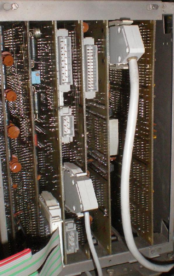
There is another thing you should check: The DIP switch settings on the RAM Board!

There are three Switch Rows, if the connectors are directed against you, the switches are on the left side.
The one nearest the connectors is A5, the middle A7 and the one farest away is A10.

A5 from the left to the right: off,off,on,on,off,off,off,off.
A7 from the left to the right: on,off,on,off,on,off,off,off
A10 from the left to the right: off,on,off,on,off,off,off,off

Please check if they actually conduct...


Regards,

Holm
--
float R,y=1.5,x,r,A,P,B;int u,h=80,n=80,s;main(c,v)int c;char **v;
{s=(c>1?(h=atoi(v[1])):h)*h/2;for(R=6./h;s%h||(y-=R,x=-2),s;4<(P=B*B)+
(r=A*A)|++u==n&&putchar(*(((--s%h)?(u<n?--u%6:6):7)+"World! \n"))&&
(A=B=P=u=r=0,x+=R/2))A=B*2*A+y,B=P+x-r;}

Dieser Beitrag wurde am 02.05.2016 um 18:36 Uhr von holm editiert.
Seitenanfang Seitenende
Profil || Private Nachricht || Suche Zitatantwort || Editieren || Löschen
122
02.05.2016, 22:42 Uhr
asbesto

Avatar von asbesto

Ehm, what do you mean with "ttl gatter"? A logic probe?
--
---
73 de IW9HGS
asbesto@gmail.com
Museo dell'Informatica Funzionante Computer Museum
http://museum.freaknet.org
Seitenanfang Seitenende
Profil || Private Nachricht || Suche Zitatantwort || Editieren || Löschen
123
03.05.2016, 08:03 Uhr
holm

Avatar von holm

No, an 7400 Slice, 7410,7420... you should combine BUS signals this way to set stop points and verify
the state of the data/address and control lines at this stop points.

Regards,

Holm
--
float R,y=1.5,x,r,A,P,B;int u,h=80,n=80,s;main(c,v)int c;char **v;
{s=(c>1?(h=atoi(v[1])):h)*h/2;for(R=6./h;s%h||(y-=R,x=-2),s;4<(P=B*B)+
(r=A*A)|++u==n&&putchar(*(((--s%h)?(u<n?--u%6:6):7)+"World! \n"))&&
(A=B=P=u=r=0,x+=R/2))A=B*2*A+y,B=P+x-r;}
Seitenanfang Seitenende
Profil || Private Nachricht || Suche Zitatantwort || Editieren || Löschen
124
05.05.2016, 10:24 Uhr
holm

Avatar von holm

What now? You gave up Gabriele?

Regards,

Holm
--
float R,y=1.5,x,r,A,P,B;int u,h=80,n=80,s;main(c,v)int c;char **v;
{s=(c>1?(h=atoi(v[1])):h)*h/2;for(R=6./h;s%h||(y-=R,x=-2),s;4<(P=B*B)+
(r=A*A)|++u==n&&putchar(*(((--s%h)?(u<n?--u%6:6):7)+"World! \n"))&&
(A=B=P=u=r=0,x+=R/2))A=B*2*A+y,B=P+x-r;}
Seitenanfang Seitenende
Profil || Private Nachricht || Suche Zitatantwort || Editieren || Löschen
125
05.05.2016, 19:26 Uhr
asbesto

Avatar von asbesto

No I'm just overhelmed by other stuff to do. I will try around next week
--
---
73 de IW9HGS
asbesto@gmail.com
Museo dell'Informatica Funzionante Computer Museum
http://museum.freaknet.org
Seitenanfang Seitenende
Profil || Private Nachricht || Suche Zitatantwort || Editieren || Löschen
126
30.06.2016, 15:05 Uhr
asbesto

Avatar von asbesto

I'm still here - paused the Robotron restore because of some other tasks I had to do.

I will try back, I hope, in a few days, checking the bus, making the ttl gatter and making some tests.

Cheers,

Gabriele
--
---
73 de IW9HGS
asbesto@gmail.com
Museo dell'Informatica Funzionante Computer Museum
http://museum.freaknet.org
Seitenanfang Seitenende
Profil || Private Nachricht || Suche Zitatantwort || Editieren || Löschen
Seiten: -1-     [ Technische Diskussionen ]  


Robotrontechnik-Forum

powered by ThWboard 3 Beta 2.84-php5
© by Paul Baecher & Felix Gonschorek